

Introduction: Jurassic Park Power Wheels Jeep - Paint / LED Lighs / Easy ESC Speed Controller


This article will cover the various steps I took to upgrade the BPRO(Battery Powered Ride-On) to look like a Jurassic Park Jeep. I will go over how I did the paint job, LED light wiring and the installation of an EastCoastPowerUp.com Easy ESC kit that features adjustable top speed, launch control, parental remote kill switch and 24v capability. This kit is supposed to be quick, easy, plug and play. I'm excited to see how it stacks up to his full ESC kit (which has been a big hit in our 24v Grave Digger BPRO)
I took an older Peg Perego Gaucho BPRO and turned it into a Jurassic Park style Jeep. The Peg Gaucho isn't an actual Jeep, but it's similar and has a lot of really cool features. This project is more inspired by the Jurassic livery and less worried about being 100% screen accurate. So please take it easy on me in regards to fact that the decals are all wrong, its not 4x4, my kid has never seen a real live dinosaur, etc etc
Step 1: Disassemble/Wash the BPRO


In the first picture here you can see the Gaucho how I purchased it. I picked up two of them in weather-worn condition for $25 each. I figured I could cobble a mostly complete unit out of the two and have a bunch of spare parts for fixing stuff down the road.
To disassemble it, I loosened the lug nuts and pulled the wheels off the axles. Then I just started taking out screws and separating the pieces. Turns out, there are quite a few pieces on one of these. Take extra care when disconnecting the wiring harness/motors/switches (don't get it wet and take notes on orientation to make reinstallation easier).
After I got everything separated, I had my little helper start scrubbing everything down. I used Greased Lightning (which is a de-greaser that helps remove stuff that keeps paint from sticking) and a scrubby brush and went to town on it. Then I hosed everything off and left it dry overnight.
Step 2: Sanding/Prep


Next we need to prepare the surface for paint. This step is very important and dictates how fine of a finished paint job you'll end up with. Skimp on prep, be prepared to have a rougher looking paint job.
This particular model was very sun-faded and had developed a scale-y gray patina. To get rid of that, I wet-sanded it with 150grit sandpaper. Wet sanding just means keeping the paper and surface wet with water as you work the sandpaper. Keeping it wet helps keep the sandpaper from clogging up with debris. This is going to be an off-road vehicle and I know how my kids treat stuff, so I skimped on the sanding. I only did two passes, one with 150grit and one with 220grit. If you want a super smooth finish coat, you'll want to do more passes with progressively higher grit sandpaper. A good order would be 150g/220g/400g/600g/800g/1200g/2000g. That's a lot of work though, so if you want that auto-show quality paint, expect to put in a lot of elbow grease.
Step 3: Adhesion Promoter and Base Coat


When you're painting something plastic that is subject to bumps and vibrations, it's a good idea to use an adhesion promoter before you paint. Without it, the paint will tend to chip and flake. The adhesion promoter is essentially an aerosol glue that helps the paint stay firmly attached to the plastic.
I started by following the directions on the can of adhesion promoter. I applied three feather light coats of it before applying a feather light coat of my base tan color. It said to lay the base paint within 10 minutes of the final coat of adhesion promoter, so I did that. I did this outdoors on a sunny/breezy day, so everything was drying fairly quickly.
I kept laying thin coats of the base paint until the coverage was thorough. You want to avoid laying heavy coats, as they will tend to sag and drip. Don't start or stop spraying while the can is over the workpiece, make sure to keep moving the can and allow a few minutes between each coat for things to dry.
I separated my parts out by color and painted in batches. 4-5 light coats on each part seemed to do the trick. Overall I used around a dozen large cans of paint and two cans of adhesion promoter.
Step 4: Masking the Stripes / Painting the Stripes


One of the distinguishing features of the Jurassic Park Jeep livery are the red stripes. After my base coat was looking good and thoroughly dry (24+hrs cure time), I worked on masking off the stripes.
I masked by using painter's tape to outline the areas I wanted to be painted red. I used a ruler and pencil to roughly mark a 4.5" wide stripe, then stuck the tape over it somewhat freehand. Once I was happy with where the tape was, I pressed firmly along all the edges and made sure there were no small spots for overspray to get through.
Once the first tape outline was masked, I taped newpaper on to cover the rest of the vehicle. Overspray sucks, so when you're working on a relatively small piece like this, it's best to just mask it off completely.
Once masked, I just went ahead and sprayed light coats of red. No need for adhesion promoter here, just go over the base coat with the trim color. I laid 4-5 coats of red and let it dry overnight before peeling the tape off.
Step 5: Reassembly


Here's where you put all the pieces back together. If you waited 6 months between disassembly and reassembly like I did, you'll find that you've made your job a good bit more difficult than necessary. Fortunately, even this relatively complicated model really only goes back together one way.
I used screws from an assortment of new screws, since the original screws were all very rusty. I also made sure to grease the axles as well as the rack and pinion steering setup.
While I was reassembling, I ran wires for my LED light setup. I used 18g thermostat wire and ran wires to headlights, taillights and underglow while I had it apart for easy wire fishing.
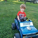
Step 6: Add Decals and Paint Is Done!


Now that it's all painted up and reassembled, you can add a few stickers/decals to complete the look. If you want a screen-accurate look, you'll need to get custom decals made by your local graphic designer/vinyl cutter. Having a perfect replica wasn't as important to me, so I just got a few off-the-shelf JP decals.
That' about it for the paint portion of this build. Next Up I'll be adding LED lights to liven things up a bit. Plus kids love flipping switches, so they're sure to be a hit.
Step 7: Run Wires for LED Lights


Since I want to add some spiffy LED Lights I'll have to have wires running to each spot that I want a light. I mostly ran the wires in between the upper and lower halves of the body, as that's where most of the factory wiring was run. I did have to drill a couple holes to get the wires out to the underglow lights.
I used 18/3 thermostat wire that I picked up from Home Depot. I like the 18/3 thermostat wire because it's cheap and having an extra wire in the bundle means you can switch two lights separately with one wire. This was handy for my headlights, which feature a larger LED head light and also a LED Halo ring, both of which have their own separate set of wires on the same fixture.
Once I had each wire fished from it's final location to under the dashboard, I would label each end with tape so I didn't have to sort them all out again later. I ended up with one wire running to the tail lights, one wire running to each head light, one wire running to each underside for the underglow strips and one wire running to each front turn signal (although I later found LEDs don't fit in there, so I just left the wire unconnected for now)
Step 8: Connect Lights to the Wires


After I had run the wires to each location, I had to hook the wire to the lights themselves. For the tail lights and underglow, this meant soldering the wires to the +/- tabs. Each LED strip can be cut/soldered every 3 inches, with one LED per inch.
For the tail lights, I stacked two 3" strips and soldered them in series. That means I connected the positive on one strip to the positive on the next, then the negative to the negative. Then I connected the feed wire from the switch to one end and another wire heading to the other tail light to the other end. This way when I hit the switch, it'll power all 12 LEDs in the tail lights.
The underglow lights were installed very similarly to the tail lights. I just used a longer strip of the LEDs and ran them along the bottom of the vehicle, one on each side. Most strip LEDs come with adhesive backing and this adhesive is usually very cheap and ineffective. Knowing this, I ran strips of 3M double-sided tape where I wanted my LEDs, then stuck the cheap adhesive side to the good 3M adhesive.
The headlights are these really neat LED "Angel Eyes" style automotive fog light. I think they'd be underwhelming on a full size vehicle, but they look awesome on a BPRO. There was no soldering required for these, they had pre-made wire leads coming out of them. I simply used my crimp tool and some butt splices to connect the wires. I like the shrink wrap style butt splices, since you can apply heat to make them waterproof. To hook the head lights to my 18/3 wire, I tied both negatives from the light to the white wire from the vehicle, then I connected each positive from the light to its own positive from the vehicle. Each positive will lead to it's own switch, so the head light and halo can be controlled separately.
Step 9: Connect Wires to Switches and Voltage Stepdown


Now that the wires are all connected to the lights, time to tidy up the other end. I started by mounting my stepdown and buss bar under the dashboard. They are the two black squares you see in the pictures. The stepdown is a device that regulates a range of voltages to a lower voltage. This particular stepdown turns 14-36v DC power into 12v DC power. This is important because I'll be running a 24v battery setup, but 24v would burn out the LEDs. With the stepdown, I can run the lights off the same battery without worrying about over-discharging one of the cells.
The buss bar isn't completely necessary, but it sure makes for an easier job of connecting the wires. It's basically just two rows of screw terminals, one for positive and one for negative, supplied with power from the stepdown.
I used some cheap switches off amazon. To mount them, I just drilled 3/4" holes in the dash and pressed the switches into each hole.
To connect the wiring, I ran the negative from each light directly to the buss bar and connected it with a spade terminal. I ran the positive from each light to a switch, then from the switch to the buss bar. I connected to the switches with .250" female crimp fittings, then to the buss bar with another spade terminal. I put small pieces of heat shrink tubing over each fitting to prevent short circuits if any wires should bump into one another during operation.
Once I had all the lights wired up, I hooked the batteries up to the stepdown and powered it up. Flipped the switches and ensured everything worked like it should. Then I went ahead and secured all my wires. I zip tied the excess wire under the dash and tucked it up out of the way. I mounted the tail light lenses with silicone. The head lights just pressed firmly into the 2.25" holes I drilled for them.
With that, my LED lights were completed. Now I just need to hook up the Easy ESC and it'll be all wrapped up!
Step 10: Test Fit Batteries and Easy ESC


Now that paint and the under-dash wiring were complete, it was time to wrap up the engine bay wiring.
I got my Easy ESC from www.EastCoastPowerUp.com. The dude that runs the site is another avid power wheels modder and is an absolute guru on the electrical aspects. I can't recommend his products enough, especially since he's got excellent customer service and is always willing to help you with any wiring issues you have. He has a full ESC kit (that I installed on our 24v Grave Digger) that I've had great success with, so I wanted to try his "Easy" version. It took me about 6 hours to install the full ESC so I was looking forward to the advertised 30 minutes install on this one.
When I opened the box, it looked very similar to the full ESC kit. The amount of wires included was a bit intimidating and I was beginning to doubt the 30 minute install claim... but once I dove into it, it became clear that this Easy ESC kit was indeed very similar to the full ESC kit, he had just done most of the wiring for you (and traded out a few advanced features in favor of more simple operation). It really did only take about 30 minutes and was very simple.
So I started by test fitting the batteries and the ESC parts into the empty bay. There was pretty much only one configuration that worked, but it fit well, so I went with that. With the big pieces in place, I screwed the ESC, relay group and potentiometers to the back wall of the bay. Then I started with the wiring.
First I connected a 10ga fuse holder to the two inside terminals to
link the batteries in series to provide 24v. His kit came with a 40A resettable breaker, but I chose to use a 40A ATC fuse. Partially because I wanted thicker wire gauge, partially because I didn't notice the 40A breaker in the box until after I had already wired up the fuse holder. If the kids start popping fuses like crazy, I'll switch to the resettable breaker.
Then I made small pigtails for the outer battery terminals. I just took a short section of 10ga wire and put a .250" female terminal on one end and a .250" ring terminal on the other. The female terminal slips over the male battery terminal and the ring terminal provides easy connect/disconnect for having multiple items attached to each terminal. With the fuse removed, I then made connections to each ring terminal. I connected the stepdown for the lights, a NOCO battery charger plug and the feed wires to the ESC. The ESC came with a charger port, but I love my NOCO chargers and prefer to put plugs on each battery so I can balance charge them.
Step 11: Connect Easy ESC to Factory Wiring


Once I had the batteries in, tied together and the accessories wired to them, I started wiring the ESC. It really only has a handful of connections to make, none of which require any cutting, crimping or soldering. It really is just plug and play.
I followed the included wiring diagram, but essentially you're removing the wires from the foot pedal switch, hooking them into heavy gauge wires that go back to the ESC, then hooking light gauge wires into the foot switch. The light gauge wires tell the ESC to turn on/off and the heavy gauge ones carry the power from the ESC to the motors. Then finally you hook the ESC up to the +/- battery terminals and it's ready to go!
The ESC provides a lot of really cool features, but my favorite is the parental remote kill switch. Now I have a little red button that I can press to shut down the ride. Kiddos heading for a head-on collision? KILL SWITCH! Kiddos about to drive through the garden? KILL SWITCH! Kiddos won't stop playing to come inside? KILL SWITCH! It even makes an awful, high pitched beeping sound when it's engaged, so the kids know that it's not just a malfunction, but a warning.
I also included some pictures here of my finished engine bay. The Gaucho has a really cool little engine cover that sits above the batteries/ESC. So the kiddos can open the hood and pretend to work on the motor without touching all the wiring. Everything fits in there so perfectly, I was really thrilled with how it came out.
Step 12: Rock and Roll!


Now that it's all done, get out there and have some fun!

Participated in the
Make it Move Contest


