

Introduction: Living Art LED Desk Lamp


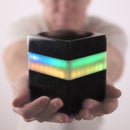

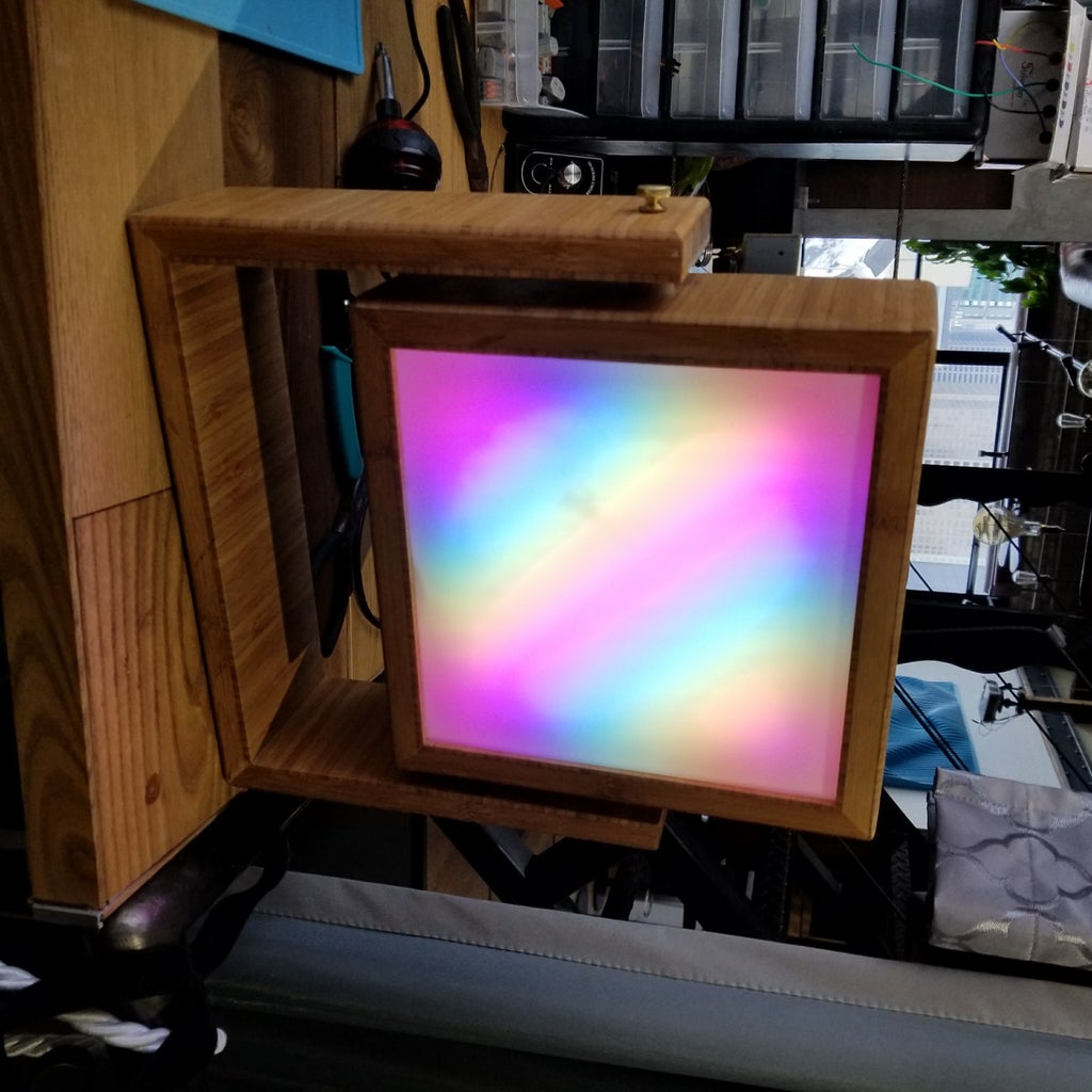
I made this “Living Art” LED lamp from plywood and an Arduino-controlled LED matrix. The Arduino Nano is programmed to creates colorful moving patterns, aka, “living art.” However, it is also practical for use as a desk lamp, table lamp, or bedside lamp, since an LED push button allows you to switch from the living-art mode to normal white-light modes, and a red-nightlight mode.
Check out the YOUTUBE VIDEO above to see ALL THE STEPS that are documented here.
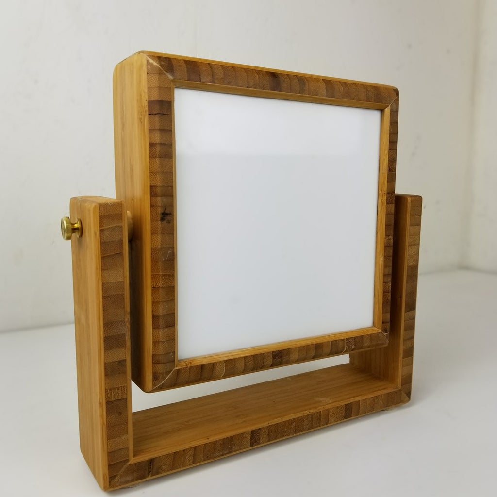
I made three versions of this lamp – two out of bamboo plywood, and one out of walnut plywood. You could use any type of plywood you like to build the lamp.
The electronics were designed to be very simple. It can be built with NO SOLDERING.
Step 1: Parts List
• 16x16 LED Matrix: http://amzn.to/2BgIcsj
• Arduino Nano: (pre-soldered) http://amzn.to/2H0h6bS
• Arduino Nano Screw Terminal Shield: http://amzn.to/2FZwy6y (pre-soldered)
• 5V Momentary LED push button: http://amzn.to/2CLbu2E OR http://amzn.to/2CLbu2E
• JST Connectors: http://amzn.to/2ALve4j
• Semi-transparent white acrylic sheet: https://goo.gl/YV4X81
• Female Power Jack: http://amzn.to/2H3oN0P (no solder) || http://amzn.to/2H3oN0P (solder)
• Lever-nut Wire Connectors: http://amzn.to/2BhMtvM
• 5V power supply: http://amzn.to/2zgiGSJ
ELECTRONICS TOOLS
• My favorite solder: http://amzn.to/2CNgjIF
• Quality Soldering Iron: http://amzn.to/2CKHoMC
• Blue Soldering Mat: http://amzn.to/2DboPCd
OTHER TOOLS I USE:
• Tap Drill Bit (for threaded holes): http://amzn.to/2Fm7V4A
• RZ dust mask: http://amzn.to/2wM8F1t
• Bosch 18V cordless circular saw: http://amzn.to/2wcDgnN
• Bosch 18V cordless Drill & Impact Driver Kit: http://amzn.to/2BCI753
• Dewalt Table Saw w/ 32” Rip Capacity: http://amzn.to/2yQd2Fy
• Japanese Flush Cut Hand Saw: http://amzn.to/2yRa1Fd
• Dewalt 12” Miter Saw: http://amzn.to/2yQRgS6
• Forstner Bits: http://amzn.to/2Bgv863
Step 2: Cut the Wood Parts


Here is the cut list for a lamp that is 9” W x 9” H x 4.5” D. You can cut from the wood of your choice, hardwood, MDF, or plywood. Note that for mitered pieces (e.g., with 45 degree cuts), the dimensions are for the longer side. Also, you could easily build this with butt joints by subtracting ¾” (thickness of the plywood) from the sides of the lamp and base that are perpendicular to the ground.
Lamp Box
- (4) sides - 9”x4.5” pieces of ¾” wood
- (1) back – 8”x8” piece of ¼” MDF
- (1) front – 8”x8” piece 1/8” white acrylic
U-Shaped Base
- (1) bottom – 11.5” x 4.5” piece of ¾” wood
- (2) sides – 10”x4.5” pieces of ¾” wood
- (2) 1” lengths of ¾” dowels
Use a circular saw, table saw, and/or miter saw to cut the above parts list.
Now go back and use your table saw to cut a 1/8” slot (i.e., the exact width of most saw blades) on the inside of each side of your lamp box, set back about ¼” from the front of the pieces. This slot will be used to hold the acrylic. (Think of it like a drawer flipped 90 degrees, so the front acrylic is installed in a similar fashion as the bottom of a drawer.)
Next, use a router or table saw to cut a ¼” rabbit on the back inside edge of each side. This rabbit will hold your back panel in place.
Use a miter saw, crosscut sled on table saw, or even a hand saw, to cut your 1” lengths of dowels. These hold the box to the U-shaped base and allow you to rotate the lamp box to direct its light.
Step 3: Make the Cutout in the Top Panel for the LED Push Button


Before we glue up the box, we need to make cutouts in our top panel for a 16mm (~ 5/8”) LED push button. This is a 5V momentary button, which will change modes on the LED matrix.
The thread on the 16mm buttons aren’t long enough to extend through the ¾” wood, so we will need to drill a larger recess on the inside of the lamp frame, in order to screw the nut to the thread on the button and attach it. Mark a center point on the top of the frame. Then use a 1-3/8” Forstner bit on the inside of the top panel to drill a hole to within 1/4” from the top (doesn’t have to be exact). Note – if you don’t have a right angle drill, you probably want to make sure to do this before gluing up the lamp box. Use the center dot in the hole left from the Forstner bit as a guide to drill through the center point with a small (e.g., 1/8”) drill bit, all the way to through the wood, which will allow you to align things when you drill from the opposite side. Now flip it over, and use a 5/8” Forstner bit to drill through the hole from the top, so you have a hole that perfectly fits the 16mm button, and is accessible to screw the nut to the button threads from inside the lamp.
Step 4: Cut the Diffuser

Cut a piece of your acrylic to 8”x 8” with a table saw, circular saw, or jigsaw. Acrylic can be cut in pretty much the same way as wood.
Step 5: Make the Cutouts in the Back Panel

First, make a ¼” cutout (or 3/8” cutout, depending on the size of your female power jack) for the threaded power jack. If your jack doesn’t extend all the way through the ¼” MDF, carefully use the same process described above for the buttons, to make larger recesses on the inside of the back panel for these two threaded jacks. Except, this time, use a ¾” Forstner bit for the recess and drill it to within 1/8” of the exterior of the back panel, and use a ¼” Forstner bit to drill the exterior hole that will snugly fit these two ¼” jacks.
If you use the pigtail power jack (so no soldering is needed), instead of a threaded jack, you don’t need to install it yet.
You’ll also cut the following holes in the pack panel:
- (optional) ¾” hole for fan intake. Drill where convenient. I centered this hole about 2” from the top edge.
- Two to three ¾” vent holes. Drill vent holes even if you don’t install a fan.
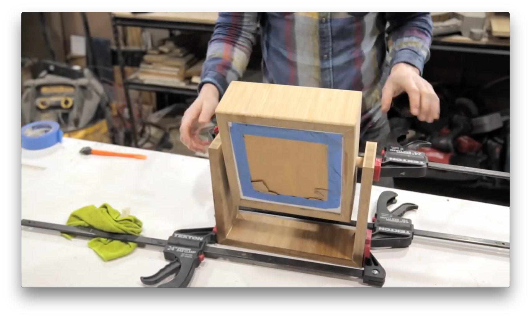
Step 6: Glue Up the Lamp Box


You will insert the white acrylic like a drawer bottom when we glue up the lamp. I suggest using the “tape-as-a-clamp” technique for gluing up mitered corners. Also, peel back just the edges of the protective plastic on the edges of the acrylic front panel, and place it on the inside of the slot on one of your lamp sides, before gluing everything up. Then apply glue to all joints, and wrap the sides of the lamp around the front panel to assemble the lamp box. See the video here: https://youtu.be/kVGqjLY0eOk?t=240 -- it is easier to show than tell.
After the glue dries on the lamp box, glue two small pieces of scrap wood to the inside back edge on each side of the box. These pieces should sit flush with the rabbit, since you are going to use them to screw the back panel to the lamp box. They should only extend about 1” from the inside surface, so they don’t get in your way later when you put the LED matrix inside the lamp.
Step 7: Prep the Holes for the Dowels in the U-Shaped Base

First, use a ¾” Forstner bit to drill ¼” deep holes on the inside of each side of the base, centered 1” from the top of on the inside surface (that will face the side of the lamp box). Also, use the ¾” Forstner drill matching ¼” deep holes on the outside of each side of the lamp box, exactly centered (horizontally and vertically) on each side. Drilling a small pilot hole first will help you get these holes dead on. Use a drill press if you have one to get these straight.
Step 8: Sand Everything and Optional Edge Routing

(optional) Before sanding I used a roundover bit on the edges of the lamp box
I then sanded everything up to 180 grit.
Step 9: Attach the U-Shaped Base to the Box


You’ll assemble the three sides of the base in the same way as you did the lamp box, except that you’ll insert (but don’t glue!) the dowels in the holes in the sides so you can use the lamp box and dowels as a brace across the open side of the U-shape, to keep the 3 sides of the base square while the glue cures. This process is shown in the video here: https://youtu.be/kVGqjLY0eOk?t=503
After the glue dries, use a thin drill bit to drill a pilot hole through each side of the U-base and into the center of each dowel. Then use a ¼” tapping bit to follow the guide holes, and drill a ¼” threaded hole through the side of the U-base and into the centers of the dowels. Now screw the ¼”-20 threaded thumb screw into each ¼” threaded hole. This will allow you to tighten the screw to lock the lamp’s positon, and loosen the screw to rotate the lamp.
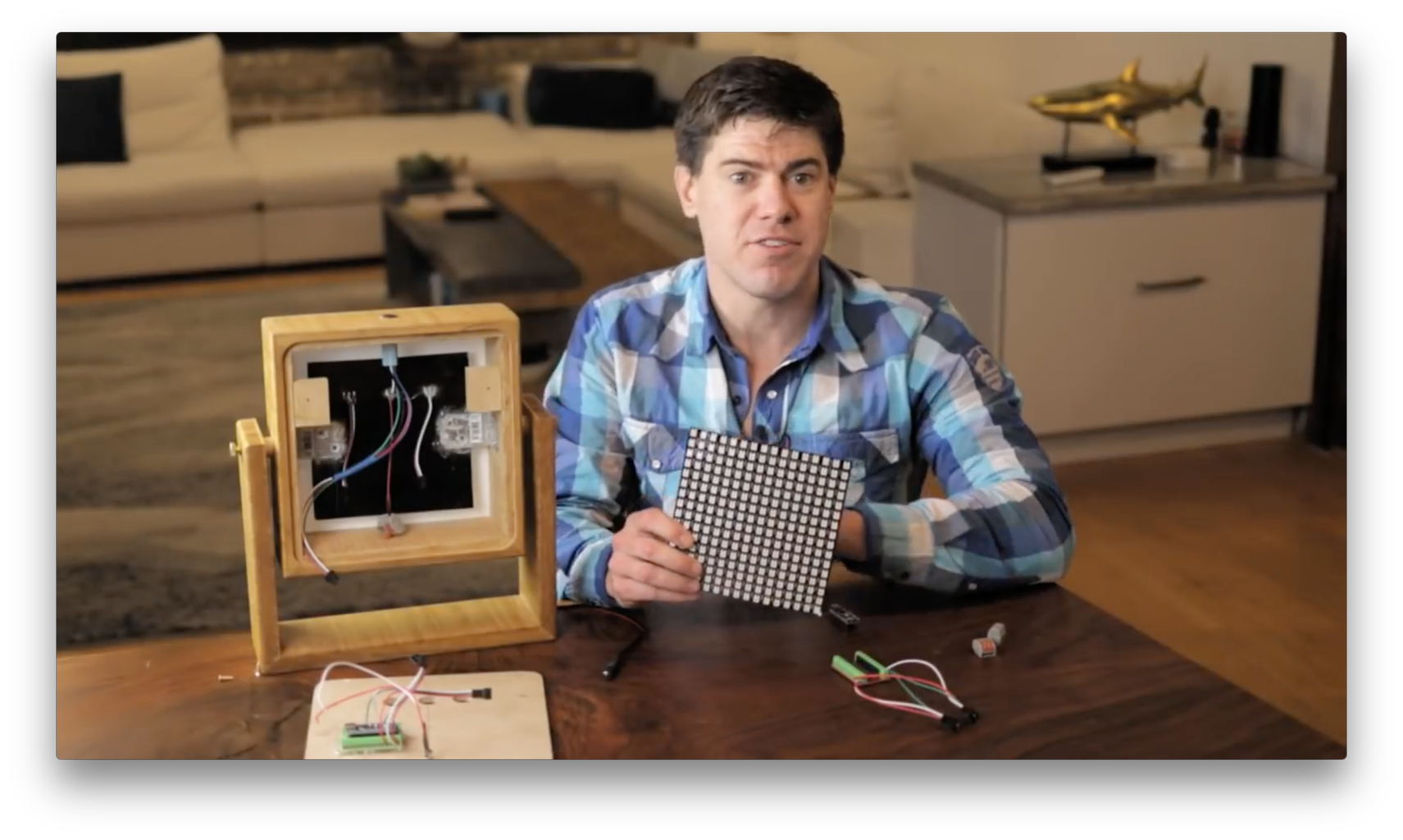
Step 10: Electronics and Code


Here is the Github link to the code:
https://github.com/modustrialmaker/Living_Art_LED_Matrix_Lamp
First, download and install Arduino if you haven't already.
Second, you'll need to add the FastLED library to Arduino. (Just search for "FastLED" in the Arduino libraries tab.)
Third, upload the Arduino code (linked to above) to your Arduino Nano. The code assumes that: (a) the LEDs are wired to pin 3, and (b) the momentary push button is wired to pin 6.
Turning to the electronics:
(a) Connect the Arduino nano to a screw shield
(b) Screw a JST connector mating to the JST on the LED matrix into the shield at pins 3, VIN, and GND
(c) Screw a JST connector mating to the JST on the LED push button into the shield at pins 6, 5V, and GND (different GND than used for LED matrix)
(d) Screw metal L brackets on the either side of the interior of the lamp box, so the fronts of the brackets are about ¾” away from the inside of the acrylic front panel. Use a hot glue gun to attach your LED matrix to the brackets.
(e) Use a hot glue gun to attach your Arduio Nano screw shield to the inside of the back panel.
(f) Connect the center power and ground lines on the back of the LED matrix to level-nut connectors (these will go to power and ground wires / pigtails from your female power jack)
(g) Take the 5V power and ground inputs from the female power jack, and connect them to a level-nut connectors to wire your jack to the LED matrix
(h) Connect the input JST on the LED matrix (it comes pre-soldered to the matrix) to the mating JST on the Arduino Nano.
(i) Wire a JST to the LED push button adapter. Red+Blue wires on push button -> green on JST; green on push button -> red (power) on JST; and black on push button -> black or white on JST (whichever yours has).
(j) Connect the JST on the LED push button to the mating JST on the Arduino Nano.
Step 11: Attach the Back Panel and Start It Up!


Insert the back panel into the rabbit in the back of the lamp box. Use screws to attach the back panel to the tabs you glued in flush with the rabbit. Plug in the 5V power supply, and fire it up!

Participated in the
Epilog Challenge 9


