

Introduction: Modular 3D Printed RC Car


I am a high school student and for my Christmas, I 3D printed my brother the Flutter Scout car. It is a remote control car that is entirely 3D printed. The following link has it's GitHub page with its parts and information about it: https://github.com/tlalexander/Flutter-Scout. This car was the inspiration for my project. The problem with this car was my middle school brother with ADD did not have the attention span to put it together and he could not keep track of all the parts. So I look for other models that had easier assembly.
I looked at OpenRC cars on Thingiverse. However, many required lots of non printed parts and importantly were not easily assembled. This project for me was about making something I could assemble with my younger brother without him losing focus.
So, I have designed a car that has several modules and combinations it can be assembled in. Currently, there are two gearbox designs, one steering assembly, and several types of tires. I have also tried to make it possible to easily add a body to the car, which I intend to design and upload soon.
Each step has attached the assembly instructions and the corresponding parts with technical drawings.
I would love to receive input from you guys and see any designs for bodies and other parts you have for the car. I would love to try them out.
If you like this project please vote for it in the Make it Move contest.
Step 1: Bill of Materials
Electronics
- 1 Brushless Motor and ESC
- 1 Servo Motor
- https://www.amazon.com/KOOKYE-Degree-Rotation-Heli...
- It is very important it comes with a star shaped horn
- 1 Three Channel Transmitter and Reciever
- 1 LiPo Battery
- Optional
- 1 On Off Switch
Filament
- PLA
- TPU
- ABS (if necessary)
Miscellaneous
- 4 10-24 Screws or 4 M4 Screws
- 4-6 (depending on gearbox) 608zz bearings
- https://www.amazon.com/uxcell-8mmx22mmx7mm-Shielde...
- These are the same bearings that are standard in skateboards.
- Propeller Adapters
- https://www.amazon.com/Onkuey-Aluminum-Propeller-A...
- You should check to see if your motor comes with them.
- Hammer
- Soldering Iron with solder
- Bullet Connectors
Step 2: Steering Assembly


Print the front chassis.
Print Settings:
- 0.3 mm layer height
- 215 C
- 30% infill
Place the servo motor into the hole.
It might be necessary to trim part of the servo motor's casing.
Print two front wheel bearing holders.
Print Settings:
- 0.3 mm layer height
- 215 C
- 10% infill
Print two front wheel axles.
Print Settings:
- 0.1 mm layer height
- 215 C
- 100% infill
- 20 mm/s print speed
- Raft without heated bed
Place one bearing on each axle.
Firmly push the bearing and axle into the front wheel bearing holders and then set aside.
Print the gearbox of your choice.
Print Settings:
- 0.2 mm layer height
- 215 C
- 25% infill
- Raft
- Support only touching build plate
- 1.5 mm wall
Fit the front chassis into the bottom slot of the gearbox.
You might need to clean up the hole and use a hammer to ensure the front chassis is secure.
It should be a tight fit
Align the holes of the front chassis and front wheel bearing holders and pass a screw through the bottom.
It might be necessary to place a nut or hot glue ring around the screw to prevent it from slipping out. Keep in mind the car has a lot of vibration.
Print the steering arm.
The steering arm is the same steering arm used in the Flutter Scout. I chose to do this because it worked extremely well and did not make sense to change. I have written permission from the designer.
Print Settings:
- 0.3 mm layer height
- 215 C
- 10% infill
Place the star servo horn on the servo motor.
Then place car so it is upside down.
Position the steering arm to it is engaged with the servo horn and so the holes line up with the holes on the front wheel bearings.
Place screws through the bottom of it.
Again, it might be necessary to place a nut or hot glue ring around the screw to prevent it from slipping out. Keep in mind the car has a lot of vibration.
The front chassis assembly is finished.


Step 3: Spur Gear Gearbox


This gearbox is easy to assemble and requires four bearings.
All of the parts are available below. The back axle is the same back axle used in the other gear box.
1:10 Gear Ratio has A Gears
fast but may require a push
1:20 Gear Ratio has B Gears
untested
First screw the metal motor mount onto the brushless motor. It is X-shaped and will help keep the motor in place.
Print the 5-tooth spur gear.
Print Settings:
- 0.3 mm layer height
- 215 C
- 100% infill
Find the propeller adapter and place the retaining ring and then the 5-tooth spur gear on it.
Secure the adapter to the motor by screwing down the nut.
Place the motor into the slot on the side of the gearbox.
Locate the rafts printed earlier or a thin piece of cardboard or wood. Cut the rafts so they fit into the slot, but are still removable.
You might need to use more than one so the motor is secure. If you use more than one, I recommend hot gluing them together.
Print the middle axle, the 22 tooth large gear, and the A1 or B1 spur gear.
Axle Print Settings:
- 0.3 mm layer height
- 215 C
- 100% infill
- Raft
- 30 mm/s print speed
Gear Print Settings:
- 0.3 mm layer height
- 215 C
- 100% infill
- If time is a constraint:
- 50% infill
- 3 mm walls
- These will wear out quicker, but are good for testing.
You should be able to pressure fit both gears onto the axle.
It might be necessary to use a hammer or to widen the hole on the gears. However, the gears need to have a tight fit on the axle.
If the gears are loose, print a scaled up version of the axle.
I plan on designing an axle with notches and clips that hold the axle in place, however until then, I recommend either hot gluing the gears and axle at a low temperature (compatible with ABS or PLA) or using super glue (compatible with PLA). The hot glue should be able to be peeled off if you want to change the gears and the super glue can be dissolved with acetone.
Place a bearing on either side of the axle.
Spread the gearbox apart and place the axle in the holes closest to the motor.
Print the A2 or B2 spur gear and back axle.
Axle Print Settings:
- 0.3 mm layer height
- 215 C
- 100% infill
- Raft
- Support touching build plate
- 30 mm/s print speed
Gear Print Settings:
- 0.3 mm layer height
- 215 C
- 100% infill
- If time is a constraint:
- 50% infill
- 3 mm walls
- These will wear out quicker, but are good for testing.
Following the same steps as the middle axle, secure the 50-tooth spur gear to the back axle.
Place bearings on either side of the axle.
Spread apart the gearbox and place the axle in the holes furthest from the motor.
Attachments


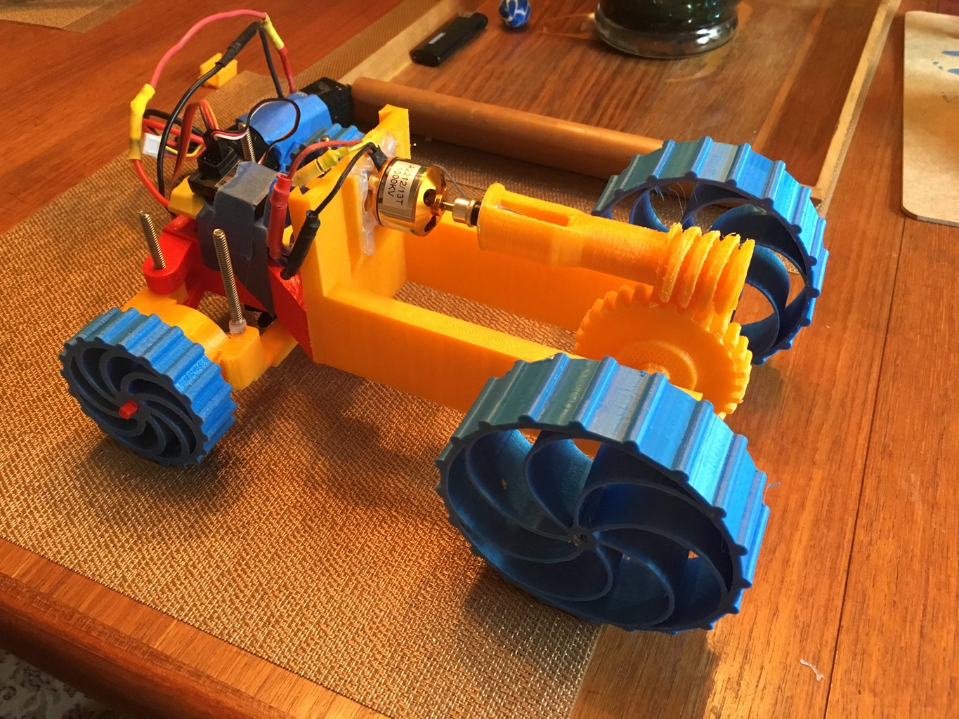
Step 4: Worm Gear Gearbox


This gearbox is more difficult to assemble. It has a 60:1 gear ratio and the gears were modified from the McMaster-Carr component library on Autodesk Fusion 360.
All the parts are available below, the back axle is the same back axle used in the other gearbox.
First screw the X-shaped metal motor mount onto the brushless motor.
Print the 30-tooth gear and back axle.
Axle Print Settings:
- 0.3 mm layer height
- 215 C
- 100% infill
- Raft
- Support touching build plate
- 30 mm/s print speed
Gear Print Settings:
- 0.3 mm layer height
- 215 C
- 100% infill
- If time is a constraint:
- 50% infill
- 3 mm walls
- These will wear out quicker, but are good for testing.
Pressure fit the 30-tooth gear onto the back axle.
It might be necessary to widen the gear's hole if it is tight. If it is loose the back axle should be scaled up so it fits. You should use a hammer to fit the gear.
You should hot glue the gear in place at a low temperature (if using PLA or ABS) or use super glue (only if using PLA). The super glue can be dissolved later with acetone and the hot glue can be removed. If the hot glue is too hot, it will melt the gear or axle making removal harder.
Place bearings on either side of the axle.
Print the worm gear.
Print Settings:
- 0.1 mm layer height
- 215 C
- 100% infill
- Raft
- Support everywhere
- 30 mm/s print speed
- If you have 2 extruders and easily soluble support filament I encourage you to use it.
Clean support of the worm gear thoroughly.
It needs to sit flat on the retaining ring and mesh easily with the 30-tooth gear.
Locate the propeller adapter and place the retaining ring and then worm gear on it.
To ensure a proper fit between the worm gear and the 30-tooth gear, you might need to add spacers to move the worm gear up along the propeller adapter.
Secure the worm gear by placing the propeller adapter on the motor shaft and tightening the nut.
Place the motor with the worm gear attached into the slot at the front of the gear box.
Cut rafts or thin pieces of cardboard or wood so they fit into the slot.
If using more than one glue them together to allow easier removal.
The rafts should be about 5 mm high than the gearbox so they can be removed if necessary.
Spread the back of the gearbox apart and place the back axle.
I know the picture is upside down, whenever I upload it, it flips.


Step 5: Electronics


Connections
Locate the brushless motor.
Solder male bullet connectors on the red and black wires. Solder a female connector on the yellow wire.
Make sure you place heatshrink around the connections to insulate them.
The yellow wire should only ever be plugged into its corresponding wire on the ESC. Changing the wires the red and black wires are plugged into allows you to change the direction of the motor.
Locate the ESC and the side with three wires of the same size.
Solder female connectors on the two lateral wires. Solder a male connector to the middle one.
Make sure you place heatshrink around the connections to insulate them. When plugged in there should be no metal showing.
Locate the opposite side of the ESC.
Solder one male connector on the red wire and a female connector on the black wire.
If you wish to add a switch, solder the red wire onto the switch. Then, solder another red wire to the other side of the switch and attach a bullet connector.
Make sure you heatshrink to insulate the wires.
Locate the battery.
Solder one female connector on the red wire and a male connector on the black wire.
Make sure you insulate the connections with heatshrink, when plugged in no metal should be showing.
Plug the wires on the ESC into the corresponding motor wires.
The Receiver
Locate the receiver, servo motor, and ESC.
In channel one plug in the servo motor so the negative (could be brown or black) is facing the outside of the receiver.
In channel two plug in the ESC's servo wire so the negative is facing the outside.
Step 6: Testing
It is easier to test the car without the wheels on it.
Prop the car up so the steering assembly and gears are not touching anything.
Turn on the transmitter.
Plug in the battery and turn on the car.
Immediately after turning on the car the servo motor should center.
If after centering, the wheels are not facing straight the following steps should be taken.
- Remove the servo horn from the servo motor with the car still on.
- Hold the wheels in a forward facing position.
- Place the servo horn back onto the servo motor so the wheels continue to remain straight.
Slowly press the throttle so the axle begins to turn.
The motor should spin smoothly if you chose the spur gear gearbox.
If you chose the worm gear gearbox, hold the throttle completely open so the motor is moving at full speed.
Run the motor for a while and it should eventually become worn in.
If the worm gear does not fully engage with the 30-tooth gear, re-position the motor and hot glue it in place or use more raft pieces.
If you have any other problems comment them and I will do my best to respond in a timely manner. It would be easier if you also attached a video showing the problem.
Step 7: Wheels


Printing and attaching the wheels is pretty straightforward.
The wheels are attached below.
Print two front wheels and two back wheels.
The back wheels are significantly larger than the front wheels to keep the car fairly level.
All Wheels Print Settings:
- TPU or other flexible filament
- 0.3 mm layer height
- 215 C
- 100% infill
Pressure fit the back wheels onto the back axle.
The square shape should ensure the wheels do not slip on the axle.
If you feel it is necessary, pins or M4 screws can be used to further secure the wheels.
Pressure fit the front wheels onto the front axles.
If you feel it is necessary, place a clip on the end of the axle to secure the wheel.


Step 8: Final Remarks
I feel the car I designed has improved on many features of the car I made my brother.
- Having a 3-sided gear box allows for easy placement of the axles and larger gears. It also remains strong given the opposing forces created by the axles and front chassis.
- The easily breakable steering pins have been replaced with screws.
- The wheels are fully 3D printed and have built in suspension.
- You can easily change the gearing.
- Overall, there are less parts to assemble and assembly is quick.
- The front chassis and it's connection to the gearbox are very strong.
However, there are some places where my car falls short.
- Some parts are harder to fit together and require the use of a hammer or the removal of material.
- Some parts need to be glued together instead of using grooves and clips to be secured.
- There is no place for the electronic components.
- The worm gear gearbox has issues with getting jammed and keeping the gears engaged with each other.
- It uses some parts that are not easily accessible like the propeller adapters.
- Some tires require rubber bands to be placed around them to gain sufficient traction.
- The worm gear gearbox had very slow acceleration and seemed to struggle getting started. However, after starting it runs fairly smoothly.
- The worm gear slipped a lot.
- None of the current tires work well on grass or ice.
- The spur gear gearbox sometimes requires a push to get it started.
- The spur gear gearbox is sometimes uncontrollable.
Things in the works
- I am working on a body for it that will be placed in the top slot on the side that articulates with the front chassis.
- I am designing my own steering arm and will update the steering assembly by August.
- I plan to design a low gear box that allows for smaller tires.
- I will create some new tire designs that work better off of pavement.
- I am drafting a new instructable on how I designed the car.
I would enjoy seeing pictures of peoples cars that they print and any suggestions or help in modifying the parts I have now. I also would greatly appreciate the creation of new modules that might allow for things like better handling or more speed. I am curious to see what body designs are created as well.
I will upload technical drawings to this step as they are completed so people can modify and create their own modules.
If there is any other information needed place it in the comments below.

Runner Up in the
Make it Move Contest


