

Introduction: Sculpted Oak Sofa


Latest in the pursuit to make everything I can for my flat... A sofa.
This piece was designed with geometry to fit what I consider a comfortable sofa; low, deep and laid back. The angular legs and sculpted arms give it an aggressive stance. Simple grey upholstery is used to compliment the modern look and draw the eye to the wooden frame rather than it. It is made from American White Oak and took a few of months working in my spare time to design and build. Enjoy..
Full build videos - Youtube
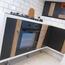
More regular updates on future projects (Kitchen next...) - Instagram @barclay5426
The rough plans I created are shown. Apologies for the image quality on some of the photos, forgot the camera for the first have of the build so they're gopro screenshots...
Materials/Hardware:
- American white oak
- Pine for the slats
- M6 Insert Nuts + Connector bolts
- Wood glue
- Danish oil
Tools I used:
- Table, mitre, circular, jig' and hand saws
- Drill + bits
- Domino jointer
- Screw drivers, spanners
- Clamps
- Angle grinder with Kutzall carving disc
- Planes and spokeshave
- Files, rasps, sander
- Measuring tape, squares, angle gauges
- Safety glasses and dust mask!
Step 1: Base and Back


The rails of the base we constructed by measuring and ripping planks to the correct length. The front rail was cut square, but the rear had to be cut with a bevel of 27° to align with the angle the rear foot splays out at.
The back support consisted of an upper and lower rail, separated by three spacers. These were again, ripped to length with a bevel. A domino jointer was used to cut tenons and the pieces glued together. Due to the beveled edges, scrap wood was clamped along the rails to give a square edge to clamp across the joint.
Step 2: Legs and Arms


Apparently I don't like designing things with 90° angles.. The lower rail of the leg rises at 5° to set the angle you sit at, is subtly tilted in and features a mitred section to change its width. The front leg and rear foot are angled both to the front/back and side. The arm angles/curves up from the top of the front leg to meet the back support..
A lot of compound cuts (mitre + bevel) were therefore required. The pieces were first cut square to the rough dimension. These were then cut to the correct angle using either the mitre saw or table saw. The front leg and rear foot needed to be tapered so were attached to a simple jig (scrap wood + toggle clamps) and ran through the table saw.
For xmas I treated myself to a Festool domino and used this to join all the components of the leg/arm assembly together. Due to the angles the pieces needed to be clamped at, temporary blocks were clamped to the pieces at an orientation that would allow a clamp to be pulled across the joint..
To give the assembly extra support a small brace was added between the arm and leg rail. This was glued and screwed in, with walnut dowel then hammered in to hide the screw. The arm/leg assemblies were now ready to be shaped.
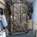
Step 3: Shaping/Finish


With the arm/leg assemblies glued up in their rough/block form, it was time to start shaping. I had a rough idea of the lines and curves I wanted to create from the concept sketches but was mainly making it up as I went and started to see what would work best in 3D.
The shaping was done using hand tools:
- A hand saw and chisel were used to rough in the top and bottom side profile curves of the arms
- A No.4 plane was then used to refine and smooth this into more of a curve.
- From there, it was a combination of a block plane, spokeshaves, gouge and rasps to sculpt in the form I wanted.
Having a right and left arm/leg assembly to try match, I decided to work on one side until it was close to finished first. I was then able to measure and transfer reference lines onto the other, to help get the same form. There was a lot of comparing and checking the two whilst shaping the 2nd and in the end they were very close to being a mirror image.
Everything was then hand sanded up to 240grit and finished with a couple coats of danish oil.
Step 4: Cushions


I've never sewn before but was keen to give it a try and make the box cushion covers myself. I bought some foam slabs and grey, fire retardant fabric. I used this tutorial, which was very easy to follow. It worked out pretty well... they're not perfect but good enough.
Step 5: Assembly


The arm/legs, base and back were connected using threaded insert nuts and connector bolts. These could have been permanently joined but I wanted the flexibility to be able to disassemble and move it easier.
- The leg and base were positioned together in the correct location
- A hole the diameter of the bolt body (+0.5mm) was then drilled through the leg into the base to create a pilot hole.
- A forstner bit was then used to drill a recess for the bolt head.
- The pieces were separated and a larger drill bit then used to widen the diameter of the pilot hole in the base
- An insert nut could then be driven into the base
- The separate components could now been bolted together. I will probably cut some oak plugs to cover the bolt head once I'm happy it not going to need moved in awhile...
Lengths of pine, the height of the front/back oak rails, minus the slat thickness, were screwed on. The slats could then be placed across and screwed down. The bottom cushion is simply placed onto the slats, the back cushion is velcro'ed to the back support to raise it up and create a gap between it and the bottom cushion.
Overall I'm very pleased with this piece, it looks good, is comfortable and sits 3 people.
Hope you enjoyed!


