

Introduction: 120v Metal Foundry With Lid Switch


I have been wanting to build a metal foundry for some time but was torn between going electric or propane until I came across This Instructable that was electric but was only 120 volts. All the other builds I had seen had been 220 volt builds or used electric elements from stoves but I wanted to use120v and a heating coil. I also liked the ability to precisely control the temp because then I could also use it as a heat treater. I came across This Build which had a nice design and some great tips that I utilized in my design. I was able to use aspects of both of these designs to create my foundry.
I tried to design this to use tools that most makers should have or give you options for those with limited tools. At most, this can be made with a hacksaw, file, snips, and drill.
I wanted to include some safety measures to protect myself. I added a switch to cut the power if I lift the lid to prevent any chance of contacting the live heating coil wires. I also added a cover over the electronics, including the heating element wires. All other designs I saw had exposed wires and nothing preventing contact with the live heating coils.
Total cost was approximately $450 and I have leftover materials and components
Caution! Using electricity to generate heat is very dangerous if contacted so caution should be taken to prevent injury. This is why you don't put a knife in a toaster.
Supplies
Material List:
Thermocouple Temperature Sensor
Tool List:
Table Saw (or hacksaw)
Angle Grinder (or hacksaw)
Drill
Snips
Pop Riveter (optional is just using screws/bolts)
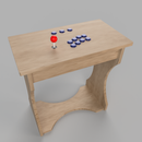
Step 1: Basic Design


I mocked up the design in SolidWorks to determine the interior size and how I wanted the layout. Many designs use 6 vertical fire bricks to create the main portion of the foundry but I wanted to use 8 to make it a little larger and give it a more rounded shape which should allow me to use up to a #6-12Kg crucible but I plan to use a #4-8Kg but I wanted the option to go larger if needed. I also designed it to use hard fire bricks as the base because they are less likely to be damaged. I was also able to determine how much material would be needed to fill the body and allowed me to determine how many rows of the heating coil I could fit which came out to be 3 rows.
I settled on this design because I liked the look and it still kept the cost down. I wanted to make a design that would utilize a hinged lid but wouldn't require welding.
I added the chart that I made when I was looking for where to get my soft fire bricks from. I went with Axner.com because I wanted a couple extra bricks and it had the best cost per brick. If you can't find bricks locally then you can check out those sites to see which is the cheapest for you.
Attachments

Step 2: Cutting the Soft Fire Bricks


Caution! Soft fire bricks release nasty dust when you cut/drill them so make sure to wear a mask when cutting these.
There are many ways that you can cut the soft fire brick to get the angles shown above. This brick is very soft so almost any blade can cut it. You could use a hand saw, a band saw, a table saw, even a lot of time with a file. I could most easily cut the angle accurately with my table saw so that is what I chose. Just make sure to use an old blade because it will dull it and a used dull blade will cut it just fine.
If you are cutting it with a power tool I recommend doing the following to help reduce the dust. Submerge the brick in water for a couple minutes until the bubbles stop and then pull them out and let them drip until it stops dripping. This will make the brick damp which causes the dust to stick together without being too wet that it sprays water everywhere. It will create a sludge but you just need to let it dry and then scrape it out. But still wear a mask.
To cut these, I set the blade angle to 22.5 degrees and then set the fence to 3.67 inches (~ 3 & 11/16 in). Then I just cut one side and flip it to cut the other side. Just make sure you are cutting off the corners on the same side. This brick cut like butter but did wear my blade.
Step 3: Cutting the Grooves for the Soft Brick


I needed to add grooves to the bricks to insert the heating element. This can also be done with a variety of tools. You can use a hand saw, router, file, maybe a band saw, or a table saw. I used my table saw because it was already used for this brick and I didn't want to dirty another tool. I just needed to make multiple cuts to create a wide enough groove. I made my grooves 0.28 inches wide and deep because the heating element I used was 0.25 inches in diameter.
For 6 of the 8 bricks, I cut three straight grooves. Two were 1.5 inches from the end and the third was in the center. I then used the other two bricks to angle the grooves so that it would create one consistent groove. See Pictures for how the angles grooves should be cut. Mark the dimensions on the smaller surface that will become the center of the foundry. Both of the angled groove bricks should be the same, one is just flipped upside down. The angled grooves should be about 60 degrees for reference.
On my table saw, I first cut the straight groove and then I set the miter gauge to 60 degrees and then marked the bricks where I needed to cut the angled grooves. I then cut a small groove along the edge of where the heating element starts and ends so that I would have a hole to feed the heating element ends through. I also cut a groove in the center of both to create a hole for the temperature sensor to fit through. It took a couple passes to make the grooves wide enough for the heating element which is why I had the two lines on either side of my measurements. My angle wasn't perfect which is why you can see they didn't perfectly line up but because these are so soft I just used a utility knife to knock off the corners to make it fit.
Step 4: Binding the Bricks


I used some band clamps to lock the soft bricks together. I couldn't find the length I needed so I bought some that I could combine to be the right size, I combined two of the clamps to make two larger clamps. I then tightened them making sure that I did not cover the holes for the heating elements and the temperature sensor. This can now be moved around and they all stay together.
Step 5: Cutting the Shell


The outside of the foundry is made of round ducting because it is cheap and already round. I needed an outside diameter of 14 inches but I couldn't find that from your average store so I just used some 7 inch ducting that I combined to give me the 14 inches I needed. I bought I 5 foot piece and then I cut it into two 11.5 inch sections for the body and two 3 inch sections for the lid. I used some cheap snips to cut the ducting.
Be careful with the snipped ducting because it will cut you. I recommend using a file to clean up the edges after you cut them.
Step 6: Adding Hardware to the Shell


The sections snap together but I wanted to make sure they stayed so I used some sheet metal screws along the seams. These screws will also help give the refractory fill something to hold onto.
I then marked the positions of the holes for the temperature sensor and heating element ends. These should be 1.5, 4.5, and 7.5 inches from the top. I drilled 1/4 inch holes for the heating element ends and 1/2 inch for the temperature sensor. (I recommend doing 3/4 in holes for the heating elements because of a problem I encountered later and had to then go back and drill bigger. The heating element ends can contact the shell if the hole is too small) I then added the terminal blocks just to the inside of the heating element holes. I attached these with some bolts I had around. I think they were #8 bolts. I then added the handles to the side. I had to bend the ends of the handles to match the diameter of the shell and had to shorten the bolts to make room for the bricks on the inside.
Step 7: Adding Temperature Sensor


I found out that the temperature sensor only needed three of the six ceramic pieces so I removed some and then attached the temperature sensor body using the same bolts as before. As you can see, the temperature sensor just barely sticks out into the main cavity. This is what I wanted as it prevents material from dripping onto the tip. The extra leads sticking out of the back will need to be trimmed.
Step 8: Electronics Mount and Cover


I needed to make a bracket that I could attach the switch onto and that would be the support for the main electronics housing. I just used some scrap steel I had but it was a strip of 2 in wide steel that I bent to be 2 inches tall and long enough to cover everything. I also added some holes on the back for the wires to go through. I later add something to the sides to cover the wires. I also mounted the push button switch on the top of it.
I mounted this with some of the #8 bolts I had. But I mounted the bolts so that the bolts face outward so that I can remove it if I need to work on the electronics at a later time.
Step 9: Adding Screws for Strength


I am going to fill the empty space with home made castable refractory so I added some of the longer sheet metal screws to the bottom where the hard fire brick will be and the short ones where the soft fire brick will be. This will help support the refractory since it is mounted in a smooth round shell.
Step 10: Hinge Bracket


I wanted to permanently attach the lid which allowed it to pivot on a hinge so I needed to make a bracket for the hinge since the body is round. I used some 1.5 inch steel that I cut to be 10 inches long and then cut grooves 3 inches in on either side. This will make it easier and more precise when I bend them. I then mounted them in my vice and bent them until it matched the diameter of the shell. I made two that were bent the same so I had one for the body and one for the lid. I then put the hinge on it and drilled 1/4 inch holes so I could both them together. I didn't want them to come undone so I made sure to add Loctite to the bolts when attaching the nuts. Again, I just used some 1/4 in bolts I had laying around.
I ended up using a smaller hinge so these brackets and the hinge are different sizes in the model I made.
Step 11: Mounting the Hinge


To mount the hinge plates, I removed the hinge pin so that I could separate the hinge and make it easier to mount the first one to the body. I aligned it so that the center of the round part of the hinge was aligned with the top edge of the body. I then attached it with some #8 inch bolts. I then re attached the hinge with the pin and then put on the lid and attached the top one to the lid. When it is closed, it sits pretty flush on the body.
Step 12: Adding the Lid Hardware


I needed a handle to open the lid and also needed something to press the push button switch when the lid is closed. This is to that when the lid is opened, it will cut the power to the heating element and eliminate the possibility of accidently contacting the live heating element which is dangerous. I modified the handle the same as the others and mounted it to the front, opposite the hinge, and then took a piece of that 1.5 inch bar and bent it to 90 degrees to push on the switch.
When mounting the bracket to push the switch, it is important to mount it so that it is fully pressing the switch down when the lid is fully closed.
I then added the long sheet metal screws to the lid to add strength for the refractory.
Step 13: Filling the Body With Castable Refractory


You want to make sure everything is attached to the shell before you fill the body.
I found this recipe on the second link at the beginning. It is just one part high temp refractory cement and 4 parts perlite.
To fill the body, I needed 8 quarts of pearlite and 2 quarts refractory cement. I also added about 4 cups water to the refractory to thin it out to make mixing it easier. It should look wet and stick together but not be runny.
I covered the work surface and the hard fire bricks in plastic wrap (Saran wrap/cling wrap) to prevent it from sticking. I wanted to be able to remove and replace the hard fire brick if they are damaged. I also added some 1/4 inch rods to keep a cavity for the heating element ends and a 1/2 in square piece of wood to keep the cavity for the heating element. I didn't want to cement any of those in place so I could replace them when they eventually wear out.
Make sure to compact it a little when you fill it. I used some small scrap pieces of wood to make sure it got all the way down into the bottom and to make sure it didn't have any voids.
Then just let it dry for a couple days. One day may be ok but I definitely recommend at least a week to really let it dry.
Some of the sheet metal screws weren't super tight even after filling it so I just put a dab of super glue on each one to really lock them in place.
Step 14: Filling the Lid With Castable Refractory


The lid required the same amount of refractory for it. I used a piece of 3.5 inch PVC pipe to create the hole in the top but you can use any round object you may have on hand. Even a plastic cup would work. It is important to make sure that the distance from the hinge to the front is the same for the body and lid so that the lid will be able to press down on the push switch. I just sketched the shape of the top of the foundry on the board I was casting the lid on so I could make sure the lid was inside the lines when casting it. If I were to do this again I would have drawn a circle on the board before casting the body to make it more round but it doesn't hurt anything being a little off round as it's just an aesthetics thing.
I used some of the cutoff pieces of soft fire brick in the middle of the lid to save on the amount of refractory I needed.
I also had some leftover refractory since I ordered an additional 1/2 gallon just in case. I used this to add a thin layer to all of the exposed fill. It just gives it a nice and smooth texture but is not required.
Because there this was a much thicker section of refractory, I let it dry for almost a week and then I baked it in the over at 250F for a couple hours and then cranked it up to 500F for an additional hour. This just helped really harden the refractory since the inside was taking so long to dry. The refractory started to lift a little in the oven so I put a baking sheet with some pans on top to hold it down.
Step 15: Add the Heating Element


To make the heating element so it fits, I measures how long the ends needed to be to reach through the body to the terminal blocks and then I straightened out double the length plus a little more on each end of the heating element and then doubled it back over itself and twisted it. This prevents that portion of the heating element from heating up since it goes outside of the foundry. I then stretched the coiled portion of the heating element until it fit all the way around in the grooves. I did this little by little to make sure I didn't over stretch it. You want to make sure the coil is stretched evenly and there are no sections that the coil is not pulled apart. Then I used some small staples that I had to fix the coil into the grooves.
I bent the ends of the heating coil into the terminal blocks and screwed them into place.
NOTE: I realized that the heating element was contacting the shell when bent so I cut the hole to about 3/4 inches and used some of the refractory cement to fill the holes but used the 1/4 in rod again to make sure to leave a hole through it. Don't want any risk of possible shock.
These heating elements may eventually wear out so that is why I made it possible to add new heating elements if it becomes necessary.
NOTE: In the last picture you can see a problem I encountered. When I twisted and then bent the ends of the heating element it stressed one of the strands and broke it. This is why I have the three pack of heating elements on the material list. They are cheap and you will want some extra just in case something goes wrong with one.
CHANGES: See Troubleshooting step on changes I made. It involves shortening the heating element to get a better heat.
Step 16: Electronics Box


I had a good amount of the leftover duct so I used that to create a box to hold the electronics and a piece to cover the sides of the electronics mount. This also made it so the electronics box matched the foundry body. I made it so that one side of the box is open so I can easily access it for wiring. I just cut this with my snips and then used a pop riveter to hold it all together (you could use the sheet metal screws). I cut the opening on the top for the temperature controller and the on switch and then cut a hole in the back of it for the wires to go through. I then made a 9 x 4 inch piece to cover the open side.
Over all the cover is 16 x 11 inches and the box side cover is 2.75 x 17
I later added some holes in the covers to allow the heat to vent out. You can see these in the later pictures. This is to prevent any heat from being trapped in with electronics and to vent the heat the SSR generates.
After I finished the build, I came across a scrap piece of steel that has vent holes in it so I cut it and made that into the side cover. It also has a electric shock warning which I thought was cool. You can see it in the cover picture.
Step 17: Wiring


Depending on the PID controller you get, this may vary some. Double check the wiring diagram on the side of the controller. I set up my wiring so that the power switch is the first thing in the line so nothing receives power if the switch is off. I ran both wires through the power switch so that the switch will glow red when the power is on. I then set up the wiring as the manual instructs but I added the push switch right before the heating element. If the switch is not pressed then the heating element can not receive power but the PID controller will still be powered.
They make power tool cables but it was cheaper and I got a longer power cable by just using an extension chord with the same size gauge wire. Just make sure the power cord you use isn't too long as it will have a greater resistance and cause the voltage to drop. I kept mine at ~15-20 feet so that I could plug it in the garage and still be able to put it out on the driveway. This also wasn't too long to affect the voltage too much.
Step 18: Assembly and Testing


I put the lid on the foundry and then it was time to cure the refractory cement. You don't want to crank it up to full temp right away because the refractory cement can bubble so you will want to run it at a low temp (~100C) for a couple hours until it stops smoking/steaming. It's hard to see but there is steam coming out in the gif. The longer you let the refractory dry, the less time this should take. The lid should already be pretty good but the body still needs to fully dry. The refractory used is water based so instead of cement that is a chemical reaction to harden, this must fully dry out to harden. I ended up realizing that you may want to heat up just the body first because the seam created softened some of the refractory on the inside of the lid. Just make sure not to make the refractory wet as it will soften.
I don't have a crucible yet, should be here soon, but I wanted to get it up and running to make sure it had no problems getting up to a decent temp. I had it set to 500C but only ran it until a little over 400C. Here are my initial notes. I forgot to remove it from the wood base I had it sitting on but even at over 400C the bottom of the foundry was just a tad warm. The exterior shell near the top was around 50C so a bit toasty but not bad. I was worried the electronics could heat too much and damage the electronics but I could put my hand on all the electronics and they were just slightly warmer than room temp.
In the end I have no concerns with the performance of this foundry. The foundry heated up just fine and everything was well insulated enough as to not damage the electronics.
Step 19: Troubleshooting

I had a little more time to run it through some heats and here are some changes I made based on the problems I encountered.
Low Temp:
I was running the foundry for a bit but it was having a hard time getting above 600C. This was rally low compared to what else I had seen. I had based my heating element on the instructable noted in the beginning and they didn't state anything about having to modify their coil so I thought I'd be good. I did some more searching and mathing and found out it was because my heating element wire was too long and thus not allowing for the right resistance. Using the coil at the original length meant it was only using about 7 amps to power it and with this plugged into a 20 amp circuit I knew I had a lot of room to increase the amp draw. This can easily be accomplished just by cutting the heating element before stretching it. If you cut it in half, then the amperage will double. I didn't want to go quite that high yet so I cut it to be 2/3 it's original length by removing 10 inches from the original length of the coil. This should pull about 10 amps so it can be run on a 15 amp circuit if that's all you have. After doing this and installing the new coil it was able to get a max temp of 900C which is plenty high enough for aluminum and zinc casting. I want to cast bronze at some point so I may cut the original coil in half to see if I can get it to 1100C which is about the limit of the bricks and the heating element. But if you do that make sure you are running it on a 20 amp circuit and not a 15 amp circuit.
Steaming Problems:
I mentioned before how the steam softened the refractory a little. Well, when I ran it it steamed a little and I had a spare brick over the hole which resulted in the steam having to escape around the lid. I didn't find out the problem until I went to lift the led and a portion of it stuck to the body (above pic). The good thing is that I could just collect the broken off pieces, add water, and then re apply it. My suggestion is now to run a temp cycle or two with a clamp on the switch and a brick or brick cut off pieces keeping the lid partially open so that the steam can escape and prevent the lid from sticking. The edges of the lid and body take much longer to heat up and thus take a lot longer to remove all their moisture. Doing a couple long heats with the lid gapped with help the steam to leave without the lid sticking afterwards.
Step 20: Troubleshooting 2


As with most projects, I continually learn how to improve the designs as I work with it more and more. I was finding it a pain when opening the lid to try and keep it from opening too far. While walking around the store I came across a door hinge stopper and realized that would be perfect to allow the lid to only open so far. It just slides onto the pin on the hinge and you can adjust it control how far the lid will open. This worked great and made it much easier when opening the lid.

Second Prize in the
Remix Contest


