

Introduction: How to Make Modern Geometric Bookends (For All Skill Levels)


I love reading, and consequently, I have a lot of books (too many if there is such a thing). It saddens me to see my beloved books toppling over, so it is time to design and make a modern bookend!
I am an Australian high school student with a love of tinkering and making things. Whilst I have some experience in Fusion 360, 3D printing, and metalwork, I will try to make this instructable achievable for a range of skill levels by demonstrating 3 different methods of producing a similar result.
When I think of modern architecture and designs, I think of sharp edges and repeating shapes, rather than the more traditional curved patterns. One of my all-time favourite shapes is an icosahedron (try saying that 3 times fast). An icosahedron is made up of 20 equilateral triangles (a triangle with 3 equal sides and angles) and forms some cool patterns to look at. For this instructable, I will be focusing on designing an icosahedron bookend, but you can choose any three-dimensional shape that has at least 1 large flat side (which will act as a base).
The main process we will follow to create this bookend is;
- Create a form or mold
- Fill it with cement/plaster (For added weight)
- Apply some form of finish (If desired)
I will cover 3 main methods of creating this bookend to suit all skill levels. Regardless of the method chosen, I will show you how I designed the model in Fusion 360 and walk you through how you can design your own custom shape. I will also provide the files to my model as well as a low-tech option for those who shy away from traditional CAD (Computer-Aided Design).
Supplies

Method 1 (Cardboard):
Step Number: 13
Materials:
- Cardboard
- Cement/Plaster
- Masking Tape
Tools:
- Pencil/Pen or a Digital Printer
- Ruler (Metal is best)
- Box Cutter/Scissors
Method 2 (3D Printing):
Step Number: 14
Materials:
- 3D Printing Filament (I used PLA)
- Cement/Plaster
Machines:
- 3D printer
Method 3 (Sheet Metal):
Step Number: 15
Materials:
- Sheet Metal (I used 1mm thick steel)
- Cement/Plaster
Tools:
- Marker
- Digital Printer
- Scissors
- Ruler
- Angle Grinder (Or a hacksaw and file)
- Welder
- Hammer
Step 1: Fusion 360 (See Step 12 for an Alternative to CAD)


The next few steps are dedicated to those of us who want to delve into the art of Fusion 360. I will step you through the entire process so even if you are a complete beginner you should be able to follow along. I am no master at Fusion so there are probably more efficient ways of doing things than I will show you, so if you know a way please leave a comment so we can all learn from you!
Step 2: User Parameters


After opening a new design in Fusion 360, the first step to any good parametric design is defining some user parameters. This way you can design your model to any scale and worry about getting the correct measurements later. Navigate to Design > Solid > Modify > Change Parameters and add a new parameter via the "+" symbol in the upper right corner. For now, we just need 1 parameter which is the side length of each equilateral triangle. However, we will be adding more later on.
Step 3: The Main Sketch


Now it is time to create a reference model. This will allow us to measure different angles and lengths we will need when making a sheet metal component later. For those who are interested in 3D printing your mould, you will be printing out the reference model so this step is still very important!

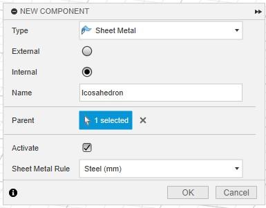
First, create the component we will work on by clicking on the New Component shortcut (Shown in the image above, underlined in green). Now that we have our new solid component we can start a new sketch via the shortcut in the toolbar (underlined in red). Start by selecting the x-axis plane. Draw a pentagon via Create > Polygon Tool. We want to centre this on the origin of the model. Using the dimension tool (Hit 'd' on your keyboard), select one side of the pentagon and set it to the user parameter "sideLength" (As this pentagon is really the base of 5 triangles as you'll soon see). Next, we want to enable the 3D Sketch option as shown below;


It's normally best to avoid 3D sketches where possible, but in this case, they serve our function well. Start by drawing 5 lines (Hit 'L' on your keyboard) starting from a point of the pentagon, and meeting at a point above the pentagon. Since an icosahedron is made up of equilateral triangles we want to use the equal constraint on one of the lines and the side of the pentagon that we have set to "sideLength" as shown below;


Fusion will then snap the model and all the other lines to the correct size. Next draw 2 lines on the front triangle that meet together (in the y-axis, i.e. straight down). If you've ever seen an icosahedron before, you'll notice the triangles on the side do not go perfectly down, but rather stick out a tiny bit, this will be done by Fusion once we start applying more constraints.
So that we don't need to manually draw this triangle for the other 4 sides, select Circular Pattern under the Create dropdown. Select the 2 lines you just sketched, then select the origin for the pivot point, and choose a quantity of 5 (As seen below);

Draw a connecting line between 2 points. Using the equal constraint, we want to define all 3 lines we've drawn as equal to the side of the pentagon with a dimension set (This will automatically make an equilateral triangle, and fusion will apply this feature to all other triangles created by the circular pattern). You can see this below;

Use another circular pattern to apply the bottom line to each other triangle. You'll notice that we have now made another pentagon on the underside of the sketch. So we'll repeat the steps we did originally and draw 5 lines from the pentagon we have now formed to a point below and set them all as equal.
Congratulations, you have just drawn an icosahedron in Fusion 360!! Make sure that you check that every line is equal to each other, you can do this by selecting a line segment and the length will be displayed in the bottom right corner (they should all be equal to the sideLength value you have defined). If you find a length that is not equal, use another equal constraint and Fusion will handle the rest. Once it looks like the sketch below you are ready to move onto the next step!


I forgot to double-check my sketch and consequently one of my side lengths was shorter than the rest, this makes some of the images shown below look slightly lob-sided. I went back and fixed it once I realised the issue but the process shown is still correct! Oops :)
Step 4: Creating a Solid Model


Now that we have a sketch, we need to make it a solid model. We can do this by first turning it into a surface model. By clicking Surface > Create > Patch, and then selecting all the faces of the icosahedron, Fusion 360 will convert the sketch into a surface model like in the images below;


To turn our surface model into a solid model, all we need to do is use the stitch function that can be found under Modify > Stitch. Select all the surface model faces, and hit enter. This will give you a beautiful solid model like the one below!

Step 5: Adding More User Parameters


Before we jump into making our sheet metal design, we need to create some more parameters. First of all, we can use the Inspect feature to measure the angle between 2 faces. Additionally, we can measure the horizontal width of the icosahedron.
The most obvious new parameter is one that stores the angle between 2 faces.
We will also need the vertical height of a triangle segment, but rather than setting that to a fixed value, we can use trigonometry to define it as tan(60)*(sideLength/2). This is because the angles in an equilateral triangle are 60 degrees.

The value "sideLength" was useful before but doesn't really tell us much about the model. Using the ratio between the side length (50mm in my case) and the measured width of the icosahedron (79.834mm in my case), we can define sideLength as 50/79.834 * desiredWidth. You can replace 50 and 79.834 with the values you defined and measured.

This also means we should create a new parameter desiredWidth and set it to our desired value. The more accurate the initial measurement of the width, the more the model will reflect the desired width. In my case, I was accurate to 3 decimal places and hence my model is accurate to +/-1mm (The larger you scale your model the more error you'll get - however, you can then manually play with the value of sideLength until it reflects your desired width more accurately and redefine the parameters).
If you'd rather control the height or depth rather than the width of the icosahedron, simply measure that value using the Inspect feature and repeat the steps above (But you can only define one dimension at a time).
Step 6: Modifying the Model for 3D Printing (Only for Method 2)


If you are interested in 3D printing your mould, you can use this reference model. First hit 's' on your keyboard to search and type in Shell. Using the shell feature you can select your component and enter your desired wall thickness. You can see some moTo check your wall thickness visually you can go to Inspect > Section Analysis and select a face of your design. This will give you a cross-section of your model as you can see below;

The final step before you are ready to export is making an opening for the cement (and a flat face to rest against the books). By opening the drop-down menu for your component, make the initial sketch visible again by clicking the 'eye'. Then select one of the pentagons you've sketched and use the Extrude feature to cut away that face.

You now have a 3D-printable model ready for the printer! Export it by right-clicking your component (In the design tree) and choosing Save As Mesh. You can skip to step 14 now that you have your STL.
(You can also find my models attached below and my STL files at printables: STL Files)


Step 7: Creating the Sheet Metal Component
This is only a short step, but it is worth noting that you should create a new component for your sheet metal model. Do this by selecting New Component but this time under the sheet metal tab. This will create a sheet metal component by default. I also copied the sketch we did previously into this new component for further reference.
Step 8: Creating Bends


This was my first time using the sheet metal tab in Fusion 360 so please bear with me if you're an expert already.
The process I used to create all the bends in this model involved starting with a Flange on one of the triangular faces. Then, I created another flange from the bottom edge of the original one. This new flange has a height set to the "verticalHeight" parameter we established earlier, and it's bent at an angle of 180 - "the angle between faces" parameter we previously set up. You can see this in the screenshot below.

Next, I created a triangle sketch on the face of the flange, this allows us to cut away the sketch giving us the triangle faces we need (Using the Extrude feature of the Solid tab). When sketching the triangles on the faces, you should always draw them from the very outer corners not from the stress relief point, as can be seen in the image below;

You will encounter some issues where you cannot create the flange you need as it intersects with the existing faces of the model. To overcome this I created a sketch that extends the face in 2D and used the Bend feature to bend it at the correct angle. In hindsight, it would probably be easier and less repetitive if you used the bend feature for all faces rather than the flange feature (Again, I am new to the sheet metal function of Fusion but you live and you learn!).


As your model starts to take shape, you can use the Unfold feature to see how the model looks when laid out flat. Fusion 360 will also add stress relief cutouts (In my case circles) on joining bends, this is important as when this is bent in metal the material will bunch up and crease in these spots, so by removing the material you get a clean bend and the hole can be filled when welding.


Step 9: Sheet Metal Rules


Once you finish your model you need to set the sheet metal rule for your design. A sheet metal rule defines the properties and thickness of your chosen material. By navigating to Sheet Metal > Modify > Sheet Metal Rules you can create a new rule based on an existing one. I chose steel as I will be using 1mm steel for my design. Then you can modify the thickness, K Factor and any other unique properties of your metal.

Now all you need to do is assign your rule. Navigate to the design tree and expand the properties of your sheet metal component. You'll find one called Rule, and by hovering over it you can click Switch Rule and choose your custom rule. Your model should update to reflect the changes!

Step 10: Exporting and Printing Your Sheet Metal Model


The final step is exporting your sheet metal design so you can print it as a template. Fusion has a built-in function for this called Create Flat Pattern which can be found under Sheet Metal > Create > Create Flat Pattern. After selecting your sheet metal component, you'll see that fusion unfolds your model into a flat sheet as seen below;


You can finish here and export your flat pattern as a DXF, but if yours looks like mine you'll notice that it isn't very easy to cut out, nor does it make the most of the material used. To fix this, we can delete existing faces and re-bend them from different adjacent sides. Any changes done to the flat pattern will not reflect in the model, you must make the changes using the "Unfold" and "Refold" functions.
By returning to the model, and unfolding it, we should get the same layout as the flat pattern generated. To help us remember which faces we want to move and where to reattach them once the model is refolded, we can modify the Appearance of a face by right-clicking it. By setting the face you want to move as well as the target face that you want to reattach it to, as 2 different distinguishable materials, you can refold your model and make the change. You can see this below;

Once you have rearranged your model, it is time to update the flat pattern and export it as a DXF. Once exported, you can open your DXF in another program (I used Adobe Illustrator) and save it as a PDF or image for printing. By adjusting the orientation of my design, I managed to fit it on an A4 page, but you might need to print it across multiple pages and stick them together afterwards.

Print your template on paper and fold it up into the desired shape. This allows you to check your design for scale before making it out of the desired material. I go into more detail about this under the "Alternative to CAD" step.
(My templates are attached below if you'd like to use them)


Step 11: The Beauty of Parametric Designs


Your fusion design is finished! Time to step back and admire your work. And the best part is we made it parametric, this means that if we update the desired width parameter, the entire model will scale for us!
There is a super satisfying video below demonstrating that:
Step 12: Alternative to CAD


As promised, there is an alternative to CAD. This is only possible for those who are doing method 1 (cardboard) or method 3 (sheet metal). If you are making a common shape, you might be able to find a "net" of it online. A net is essentially an unfolded diagram of the shape.
First print off the net (or draw it by hand) onto paper and then cut it out and fold it into the intended shape. Using some tape you can stick together your reference template. Make sure you have an opening for the cement to pour into (You can see how my paper model in the image above has some panels missing). This opening needs to form a vertical edge when standing in its intended upright position (to rest against the books). Then get your favorite book and see how the paper template looks for scale. Once you are happy with your template, you can move on to your method-specific steps below.


(I have attached my templates below if you'd like to use them)

Step 13: Cardboard Method


By now you should have a template that you've either printed or drawn by hand. By cutting a panel off a thick cardboard box you can begin to trace the outline of your template. After you've traced the outline, you should also draw the bend lines, you can do this by using a ballpoint pen and applying a bit of pressure on the paper template, this will leave light marks on the cardboard underneath. Now cut out your template using a box cutter or scissors!

Using a ruler, you can press down on the previously drawn bend lines. This will compress down part of the cardboard without needing to score it. Before you go ahead and bend the cardboard into its final shape, I highly recommend first bending each segment to make it more flexible.


Fold your cardboard into the intended shape and stick it together on the outside with tape. Make sure you use additional tape to seal up any gaps (Stick tape on the outside so that it doesn't imprint on the cement).


You can skip to step 16 for pouring cement and some final words of advice!
Step 14: 3D Printing Method


Now that you have your STL (You can find my STL and some printing advice by clicking the following link: STL Files), it is time to slice it and print it. For anyone with a 3D printer, this method is probably the simplest and easiest of all 3. The advantage of 3D printing is you can print it in any colour(s) that you want! Make sure you use a rigid filament that isn't super flexible, and you use at least 3 walls/perimeters to prevent water leaking from the cement/plaster when casting.
Once you've printed your model, you can skip to step 16 for pouring cement and some final words of advice!
_________
On a side note, this 3D-printed mould makes a good plant pot too! Here are some photos:


Step 15: Sheet Metal Method


This is the most complex method but is still doable so long as you follow this process. First, trace your paper template onto your sheet metal. Remember to drill holes at all the stress points that Fusion generated. If you don't have a sheet metal bending brake (which I don't) make sure you score the bending lines. I cannot stress how important it is to make deep scores, mine weren't deep enough initially and caused a ton of struggle. Make sure your scores are over halfway through the material thickness. Then you can cut out your piece of metal.


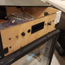
Using a hammer and a pair of pliers, start bending your piece of metal into shape. You can tack-weld edges together as they meet to help the sheet metal keep its shape. You might also find using a piece of round bar helps to hammer edges that are hard to get to. It should begin to look like the following (It can take a while):


I ran into 2 major issues. First, I had cut one of the triangles too short, and hence 2 faces had a huge gap that I couldn't bridge with weld. And second, I didn't originally score my bend lines deep enough. To fill the gap, I ground down a small offcut into a thin length of metal and welded that across the void. I was too far into the bending process to simply unfold and rescore my lines, so I did a 'reverse score' and ground down some of the material from the outside, this meant the bend line had an overall smaller thickness, but it also meant I needed to weld over those grinds at the end to get a sharp meeting edge.


Once you've formed your metal into its desired shape, it is time to weld all the edges. I deliberately added too much weld so that I could grind back sharp corners. You should do all your welds on the outside, and then hold it up to the light to look for any gaps in your welds. These gaps can be filled by welding on the inside. I had a nasty hole on one of my points, but with enough patience and weld, anything can be fixed!


Since we are pouring cement into this mould, we want to weld some old screws on the inside to act like rebar. These will give something for the cement to grip on to, giving it additional strength and making it less likely to rattle around inside the mould once cured. I am using flux-cored welding wire, which makes a bit of a mess on the inside, but it doesn't matter as we'll be filling it with cement.


The final step before your beautiful metal mould is finished is to get out the grinder and grind back all your welds to reveal the mould's true shape. This lets you form those sharp, modern-looking, edges. Then get out a file to fix any imperfections and round over any jagged edges or points. And finally, a quick hand sand to smooth out any grinding scars.


Time to move on to the next step for the cement pour!
Step 16: Adding Cement


By this stage, you should have a mould ready to cast (or multiple if you are making one for each end). Before mixing the cement, dig a shallow hole for each mould in some sand for the mould to rest in. This is especially important for the cardboard moulds as the water content in cement will cause the cardboard to deform slightly. I cut out some holes in a cardboard box so that my moulds would sit flat when filled with cement but I would recommend against this, as the cardboard box tore under the weight of the cement (and juggling wet cement-filled moulds whilst trying to find a way of propping them up isn't easy!). I've included an image below of what not to :)

For those who don't already know, cement will stick to all your clothing, so wear an apron and old clothes whilst also working outside! Cement is also corrosive so make sure you wear a respirator to protect your lungs, gloves to protect your skin, and safety glasses to protect your eyes!
Now it's time to mix your cement. I only had concrete on hand, so used a metal sieve to remove the blue metal from the sand (as I didn't want the rocks to show through). Measure out the required amount of cement by using one of your moulds as a scoop (or just guess), then add a little extra given you'll probably spill some and some will stick to the edges of the container you mix it in. Add water as instructed by the packaging. Then pour it into your moulds. Remember to tap and vibrate your moulds to get rid of any trapped air bubbles!


After a few hours, you can use a rag to wipe off any excess cement on the outside of the moulds (you don't need to do this if you are casting them in cardboard). However, if you are doing method 1, you should remove the cardboard after 24 hours or when the cement has almost fully set (but not entirely), this makes any sanding in the next step way easier. If you are doing method 2 or 3 you can wait until the cement has fully set as it remains inside the mould.


You could also use Plaster of Paris as a replacement for cement, but cement is heavier and stronger. If you need any additional weight, you can fill your mould with old steel parts (such as rusted screws or bent nails) whilst leaving some space at the top (so they don't poke through) but only do this for method 2 or 3 as you don't want the nails to show through in your final bookend.
Step 17: Applying a Finish


The final stage of this project is to apply a finish, paint or sand down your cast into the final shape.
Method 1:
If you haven't already, remove the cardboard from the cement. This reveals your masterpiece! Whilst wearing a mask in a ventilated area, you can sand down the edges of the mould to smooth and shape them. If your cement hasn't been fully set yet (as sanding softer cement is much easier), leave your cement to cure fully. Once cured, you're done! You can paint it if you desire but I love the raw cement look (as seen below). I did however brush some watered-down wood glue to help hold any loose sand on, and give it a glossy finish.
 →
→
 →
→ 
Method 2:
Once the cement has fully cured you're done! If you've spilt cement between the layer lines (and couldn't wipe it off whilst it was still wet) you can paint over it (I recommend against sanding as the microplastics are incredibly harmful to both you and the environment). If you don't like the cement appearance from the opening, you can print a cover and friction-weld it in place (or weld it on with a 3D pen), or you can sand and paint over the cement. I chose to paint it all black as you can see below:
→
 →
→ 
Method 3:
Now that the cement has fully cured you are left with a few options. You can cut a steel "lid" to cover the cement edge and polish the steel to a beautiful mirror finish (or paint over it). Or you could sand down the cement to a smooth finish. and spray paint the entire bookend a desired colour. I don't have a buffing wheel so opted for the latter option as can be seen below:
→
 →
→ 
Step 18: Final Comments


Congratulations, you've made modern geometric bookends! I am very happy with how mine turned out. The raw cement one isn't quite as smooth as the other 2 methods, and the metal one feels much nicer to hold and doesn't have the layer lines like the 3D printed one does. All 3 methods worked really well, and the results are as expected!
Not only are they great bookends but I've used mine as a bookstand and to hold up my chopping boards.
Thank you for reading my instructable and I hope you learned something about Fusion 360 or DIY projects. Your house is sure to look even more beautiful than before, and your books will now thank you :)
Be sure to share your makes and any tips or questions below in the comments. You can find all the templates I designed reattached below, as well as the link to the STL's and models for anyone interested in them.
Happy making!


This is an entry in the
Books and Bookshelves Contest


