

Introduction: 3D Print Embossed Pattern Cookie Rollers


Embossing rollers are great for cookies, pies, fondant, and clay. With one easy roll, you can transform your doughs and fondant into masterpieces! In this instructables I am going to show you a easy solution into creating your own embossing rollers with the use of Fusion 360 and a 3d printer.
Step 1: Project Requirements
- Download a free hobbyist version of Autodesk Fusion 360
- Vector Program such as Inkscape (free) or Adobe Illustrator (Paid)
- 3D Printer
- PLA or PETG Filament
- Alumilite Clear Cast
- Latex Gloves (get from your local hardware store or Amazon)
Step 2: Create Roller Rod
1. In Fusion 360, start by going to the Create Menu and select Cylinder.

2. Set the diameter to 15 mm (0.19685") and the height to 127 mm (5")
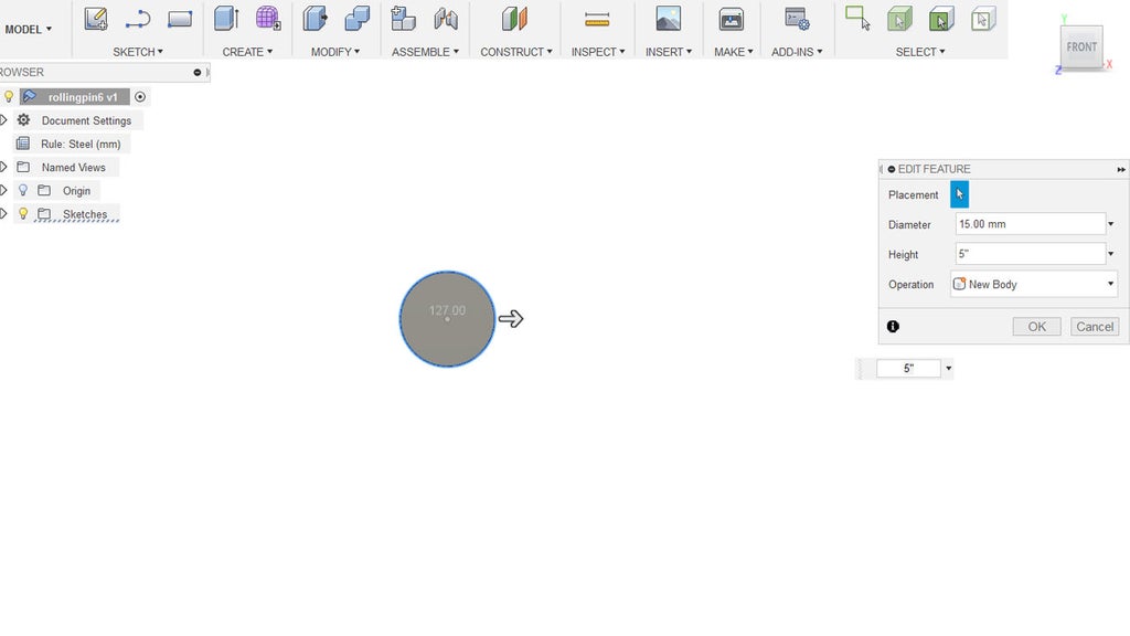
3. Create a new cylinder at one end of the rod. Set the diameter to 15 mm and the height to 10 mm. Set operation to New Body. This cylinder will be used to create a threaded end for the rolling pin rod.

Step 3: Create Threads of the Rod
1. In the Create Menu, select Thread.

2. Select the outer face of the cylinder to be used for the threaded end. Check the Modeled feature checkbox and use suggested parameters.

3. Select the threaded end. Press Ctrl + C (PC) or Command + C (Mac) to copy the feature. Press Ctrl + V or Command + V to duplicate the feature and enter into the Move/Copy function. Move the duplicated threaded model to the opposite end of the rod.

4. Under the Modify Menu select Combine.

5. Select the rolling pin rod and the two threaded ends. Set the operation to Join and click okay.

Step 4: Create Handle
1. Create a cylinder over one threaded end. Set the operation as a New Body with a diameter of 26 mm. Place a minimum height of 20 mm.

2. At the outer end of the new cylinder created, create an additional cylinder with a 26 mm diameter and a height of 30 mm. Set the operation to New Body. Hide previous cylinder.

3. Go to the Modify Menu and select Draft.

4. On the 30mm cylinder select one end. The select the outer cylinder. Rotate the angle to create a taper effect on the cylinder. Set the angle to something like 10 degrees.

5. Unhide the 20mm height cylinder. Combine the tapered cylinder to the 20 mm cylinder.
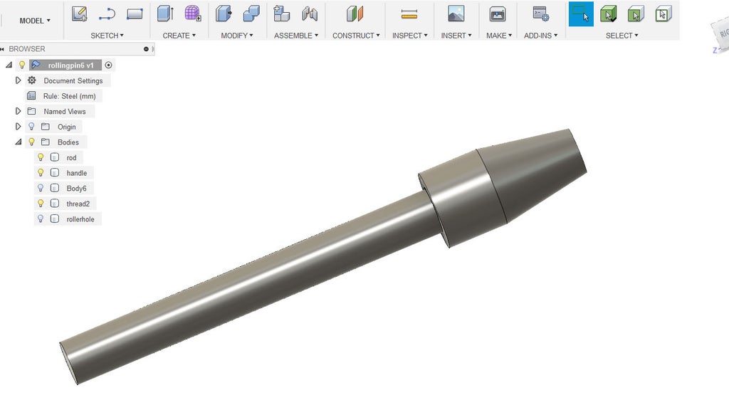
6. Optional. Go to the Modify Menu and select Chamfer. Select the edge that connect the taper cylinder to the 20mm cylinder. Set to 5mm distance.

Step 5: Create Handle Threads
1. Hide the rolling pin rod. At the bottom end of the handle create a cylinder. Set the diameter to 16.5 mm and the height to -10mm. Set the operation to cut so the cylinder cuts into the handle.

2. Go the the Create Menu and select Thread. Check on Modeled. Verify that the designation is M16x1.5 and press okay.

Step 6: Create Roller
1. In the Sketch Menu, select Circle > Center Diameter Circle.

2. At one end of the rolling pin rod, from the center drag out a circle. set the diameter to something between 45 to 50 in diameter.

3. Hit L on your keyboard to bring up the draw line function. Draw a line from the center of the circle to a little beyond the end.

4. Hit O on your keyboard to bring up the offset command. Select the line you just made and et the offset to 1 mm.

5. Hit T to bring up the Trim command. Select the edge of the circle between the two lines to remove it.
6. Hit X on your Keyboard. Click the two lines to convert into construction lines. Press Stop Sketch.

7. Change Environment from Model to Sheet Metal.

8. Go to the Create Menu and select Flange.

9. Select the circle sketch and set a distance of 127 mm (5"). Press Okay.
10. Select the faces one one side of the cut in the cylinder. Hit E on your keyboard to bring up the Extrude command. Change the operation to join. Set a distance to 0.75 mm.

11. Go to the Modify Menu and select Unfold. This will flatten the cylinder.

12. Using the Inspect tool, measure the x and y distances of the flatten cylinder. In this case the flatten cylinder is 148.089 mm high by 127 mm in width. This measurement will be used for the pattern creation.

Step 7: Create Pattern

1. Open up your vector program of choice and make a 148.089 mm high by 127 mm in width document.
2. Set guidelines up about 4mm inwards from both sides of the document.
3. Start designing your pattern.
Step 8: Export Pattern

Export your pattern as a DXF. If the DXF format is unavailable in your program you can save out as a SVG.
Step 9: Import Pattern


1. Go to the Insert Menu and select either Insert SVG or Insert DXF depending on the format of your pattern. Since I saved out as a DXF I used the Insert DXF feature.
2. Set the Units to the units of the design document. In my case Millimeters. Move the design onto the flatten cylinder if it imported off centered. Press okay when finished.
Step 10: Cut Out Pattern


1. Hit E on your keyboard to bring up the Extrude command. Select the faces of the pattern sketch.
2. Set the Distance to -1.5 mm and the operation to Cut to subtract from the roller. Press OK when finished.
3. In the Menu bar click on Refold Faces to unflatten the cylinder.
Step 11: Clean Up Roller
1. Select faces of one edge of the gap of the cylinder. Press E on your keyboard to bring up the Extruder command feature.
2. Change Start to Profile Plane. Direction to One Side. Extent to To Object. Set Object to the adjacent faces of the gap in the cylinder. Set Distance to (TO). Chain faces to Extend Faces. And set Operation to Join. Press OK when done.

3. Select the faces of where the gap was. Press delete to delete these faces.

4. At one end of the roller create a cylinder. Give it a diameter of 20mm and a length of 140 mm or more. This will be the cutout hole for the roller for the rod.

5. Change the design environment from Sheet Metal to Model.
6. Under the Modify Menu select Combine.
7. Select the roller and then the cylinder for the hole. Set the operation to Cut. Press OK.

8. Select the Edges of the roller. Press F on your keyboard to bring up the Fillet command. Set the fillet to 1 mm to round the edges. Press OK.

Step 12: Export Parts

Click on the Make button in the Menu bar. This will bring up the STL export for 3d printing. Select the object you want to export and press OK. Export the Rod, Handle and Roller.
Step 13: 3D Print Parts

Import the models into your slicer of choice. Make sure to print 2 versions of the handle. For strength, I recommend printing the rolling pin rod on its side. To keep the rod well rounded, change your overhang angle to 15 degrees or less and print the rod with supports. If you can, change the support resolution to 2mm for print supports for the rod.
Print Settings:
Layer height: 0.3mm
Fill: 15%
Supports: Yes (for the rolling pin rod)
Rafts: Optional
Step 14: Post Process

Once the 3d prints are complete, remove any print supports. Sand down any blemishes.
Food Safety Note:
Wash with soap and water prior to use. I highly recommend sealing the prints with a food safe epoxy such as Alumilite Amazing Clear Cast.
Using Alumilite Amazing Clear Cast.
With gloves on, I applied a medium coat of the epoxy mixture (1:1 Ratio) and let it cure 48 -72 hours before use. I kept the prints on tinfoil and turned them every so often so as to not cure themselves to the foil. Alumilite Amazing Clear Cast has about a 30 minute work time.
Step 15: Results


Once the prints are read, screw on one handle to the rod and add roller. Screw on other handle to opposite side. Now you have a unique embossing pattern roller for your creative projects.
Want to skip the design phase and just print? Your can find designs on Myminifactory.com and myminifactory.com/users/twiesner

First Prize in the
Plastics Contest


