

Introduction: AS5600 Magnetic Angle Encoder


This instructable explains how to measure shaft angles using an AS5600 magnetic encoder and an Arduino UNO R3 microcontroller.
Multi-turn (total-angle) measurements are supported.
The AS5600 is capable of 12-bits resolution which equates to 360/4096=0.087 degrees. This resolution assumes ideal magnet positioning and no distortion of the magnetic field. In practice I observed variations of up to 2 degrees which can be reduced using interpolation.
A method for reducing these errors to less than 0.5 degrees is explained.
The STL files for the test-jig sensor-mounting bracket and magnet-adapter are included.
The cost of the AS5600 sensor module, magnet, and I2C level converter is less than $5.00
Images
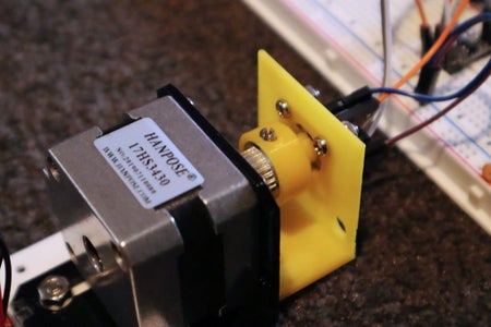
- Photo 1 (cover) shows the magnetic encoder attached to a NEMA17 stepping motor
- Photo 2 shows the rear view of the encoder
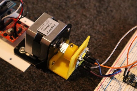
- Photo 3 shows the calibration test jig
- The video shows the encoder in operation
Supplies
The following items were obtained from https://www.aliexpress.com/
- 1 only AS5600 encoder complete with diamagnetic magnet
- 1 only I2C logic level convertor
- 1 only Arduino UNO R3 complete with USB cable
- 1 only Big Easy Driver motor controller
- 1 only NEMA17 17HS3430 stepping motor
- 1 only NEMA17 mounting bracket
The following items were on hand
- Arduino jumper wires
- 4 only M3 x 9mm threaded nylon spacers
- 8 only M3 x 5mm bolts
- 4 only M3 x 10mm bolts
- 2 only M3 nuts
- 4 only M4 x 10mm bolts
- 2 only M4 nuts
The cost of the AS5600 sensor module, magnet, and I2C level converter was less than $5.00
Step 1: Theory

Magnetic encoder chips contain two (or more) Hall sensors at right angles to each other. [1]
The construction of a hall sensor is such that an output voltage appears whenever a semicoductor channel experiences a perpendicular magnetic field.
The amplitude of this voltage decreases to zero when the magnetic field is edge-on.
Reversing the magnetic field reverses the voltage.
Rotating a Hall sensor within a constant magnetic field produces a sinusoidal output.
We get the following outputs if we orientate two sensors at 90 degrees to each other.
Sensor1 = I = sin(A) ……….………………..............……. (1)
Sensor2 = Q = sin(A + 90) …..…………………................. (2)
Where
- A is the angle of the Hall sensor with respect to the magnetic field
- I is the in-phase output
- Q is the quadrature (90 degree) output
Expanding (2)
Sensor2 = Q = sin(A)*cos(90) + cos(A)*sin(90)
= sin(A)*0 + cos(A)* 1
Sensor2 = Q = cos(A) ………………….......................... (3)
Divide (3) into (1)
sin(A)/cos(A) = tan(A) ………………….................……... (4)
We can now calculate angle A
angle A =atan2(Q, I) ………………………............…..…...(5)
Note
[1]
It is possible to make your own magnetic encoder by mounting two linear Hall sensors at right-angles to each other.
Photo 1 shows the Arduino ADC (analog-to-digital) readings for two 49E sensors mounted at right-angles. Note that the mid-point of each sinewave is approximately ADCmax/2 = 1023/2 = 512.
Integrated circuits, however, are preferrable because the sensors can be placed closer together, and are precisely aligned, which results in higher precision.
Step 2: Circuits
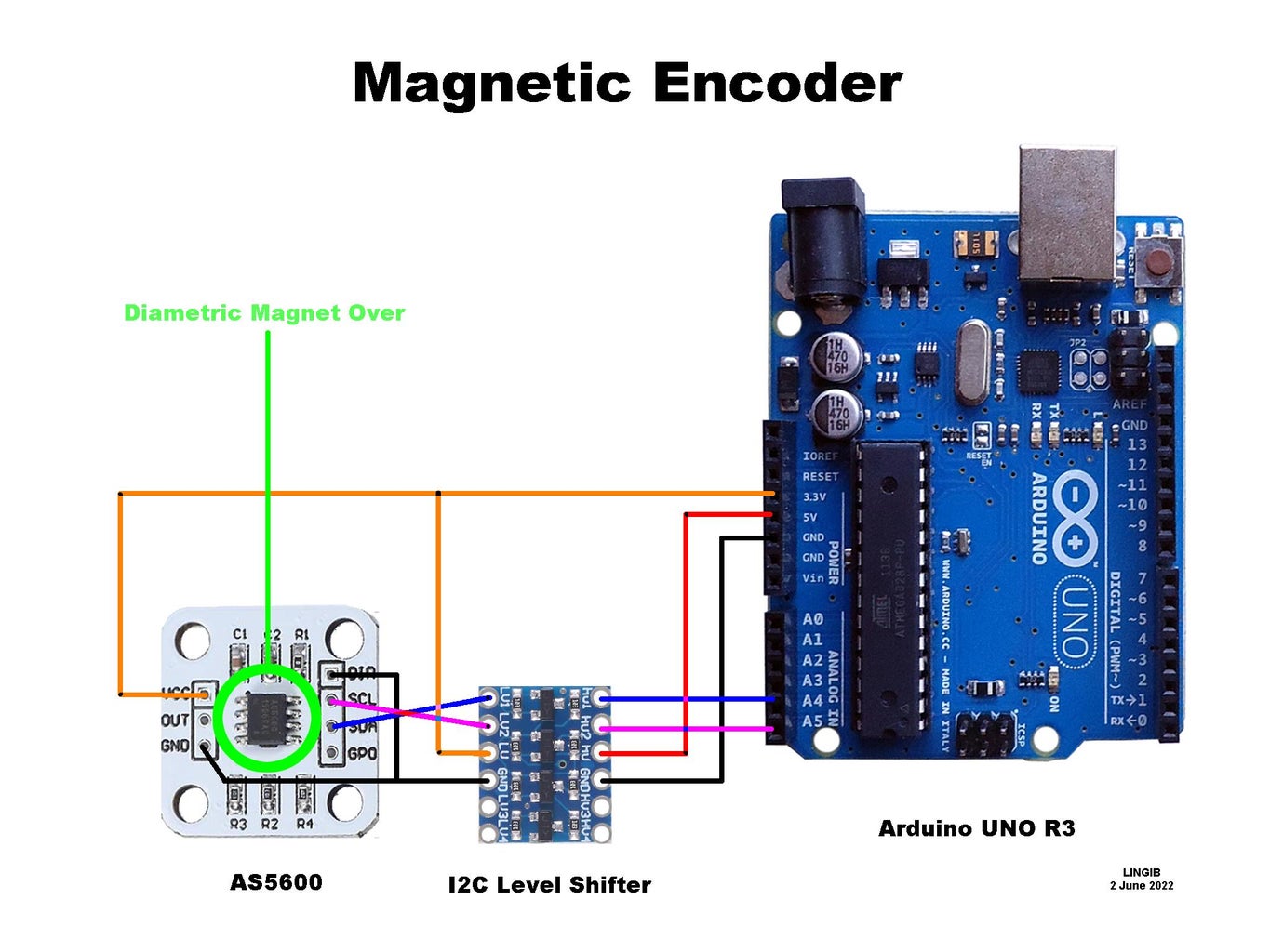
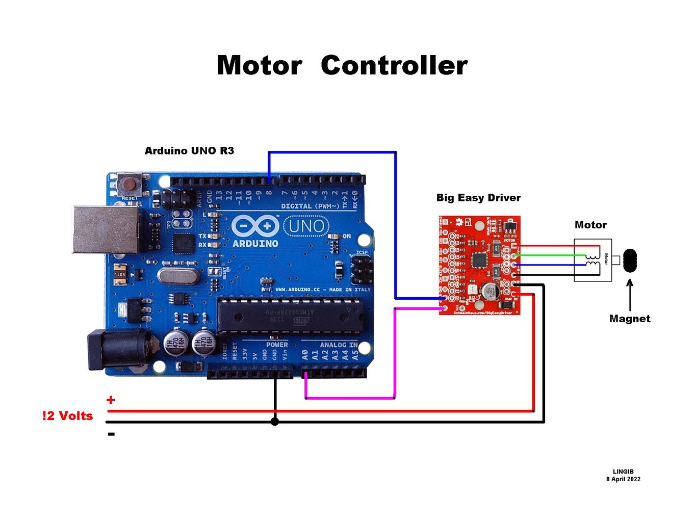
Photo 1 shows how to connect the AS5600 magnetic encoder to your Arduino Uno R3
The I2C level shifter is not required when using a 3.3 volt microcontroller.
Photo 2 shows how to connect the Big Easy Driver and motor to your Arduino R3.
Step 3: STL Files


The following STL files are attached to this step:
- Photo 1 … “ AS5600_magnet_mount.stl”
- Photo 2 … “AS5600_pcb_mount.stl”


Step 4: Assembly

Magnet mount
- Replace the grub-screws in a GT2-20 timing pulley with M4 bolts (I cut mine down)
- Attach the magnet mount to the GT2-20 timing pulley as shown in photo 1.
- Press the diametric magnet that is supplied with each AS5600 breakout board into the hole at the end of the 3D magnet mount.
PCB mount
- Attach the PCB to the PCB mount with two M3 x 10mm nuts and bolts as shown in photo 2
- Attach the PCB mount to the NEMA17 stepping motor with two M3 x 10 nuts and bolts
Adjust the magnet distance
- Loosen the GT2-20 grub-screws and slide the timing pulley back/forth for a 2..3mm gap between the face of the magnet and the AS5600 sensor chip.
Step 5: Software
Installation
- Download the attached code “AS5600_interpolation.ino” [1]
- Copy the contents into a new Arduino sketch and save the sketch as “AS5600_interpolation” (without the quotes). Use a text editor such as Notepad++ …nota word processor
- Now compile and upload the sketch to your Arduino
- Done …
Run the software
- Apply 12 volts to the motor
- Adjust the motor current limit on the Big Easy Driver motor controller to 400 milliamps (0.4 amps) using the current-limit potentiometer on the Big Easy Driver
- Open your Ardiono IDE (Integrated Development Environment) and left-click “Tools | Serial Monitor” and set the “baud speed” to 115200.
- The motor should turn and measurements scroll down the screen each time you click “Tools | Serial Monitor”
- The calibration values are the first set of readings taken at 9 degree intervals. [2]
Notes
[1]
Code
- The AS5600 code is from https://curiousscientist.tech/blog/as5600-magnetic-encoder-a-practical-example
- The motor control code is a modified version of my https://www.instructables.com/4-Wire-Horizontal-Plotter/
- The interpolation algorithm is mine.
[2]
Providing your project has a home position (i.e. the motor always starts from the same position) the calibration values can be permanently written into the header array.
Attachments

Step 6: Error Correction

The graph in photo1 shows the measured and corrected angles for my AS5600 magnetic encoder.
A calibration table was created by rotating the magnet at 9 degree intervals and recording the sensor values into an array[]. These values are shown in the attached file “AS5600 Error Correction. txt” along with measurements taken every 50 micro-steps [1]
Let’s correct the reading of 176.04 degrees we measured at 1550 motor (micro) steps.
The Actual Value
The actual angle at 1550 microsteps is 1550/3200*360 = 174.38 degrees
The measured error is therefore 176.04 – 174.38 = 1.66 degrees …………………….. (1)
The Interpolated Value
The measured reading of 176.04 lies between the following values in our calibration table
array[19] = 172.72
array[20] = 182.11
Since the array readings are 9 degrees apart the interpolated value is
Interpolated value = index-of-array[19] * 9 + (measured – array[19])/(array[20] – array[19]) * 9
= 19 * 9 + (176.04 – 172.72) / (182.11 - 172.72) * 9
= 171 + 3.33 / 9.39 * 9
= 171 + 3.19
= 174.19 degrees
The interpolatederror is therefore 174.38 – 174.19 = 0.18 degrees …………………. (2)
Photo 1 shows the corrected readings in red [2]
Notes
[1]
A NEMA17 motor requires 200 steps/revolution or 1.8 degrees/step
With 16x micro-stepping each revolution takes 200*16 = 3200 micro-steps
[2]
This error-correction technique can be used with any sensor.
Attachments
Step 7: Summary
This instructable explains how to measure a rotational angle of a motor shaft using an AS5600 magnetic encoder and an Arduino UNO R3 microcontroller.
The software supports multi-turm (total-angle) measurements
The AS5600 is capable of 12-bit resolution which equates to 360/4096=0.087 degrees.
This resolution assumes ideal magnet positioning and no distortion of the magnetic field. In practice variations of up to 2 degrees have been observed.
An interpolation algorithm for significantly reducing these errors is explained.
Click here to view my other instructables.

Participated in the
Build a Tool Contest


