

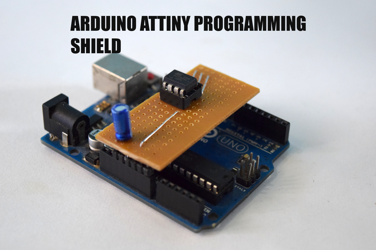
Introduction: Arduino Attiny Programming Shield


An Attiny is a great alternative to the atmega328, it is for those projects that need few GPIO pins and need to be portable. But unlike the atmgea328 the attiny cannot plug into an Arduino board and be programmed. Another way would be to use a breadboard and an Arduino uno as ISP, but it would be really messy and it would be hard to program it this way multiple times.
A better way would be to program it on a shield and in today's instructable I'm going to show you how to build an attiny programming shield. The shield is easy to build and plugs on to an Arduino to program. So all you have to is plug the attiny on the IC Holder and you can program it.
You can also check out the video tutorial on how to build this below.
Step 1: Tools and Components
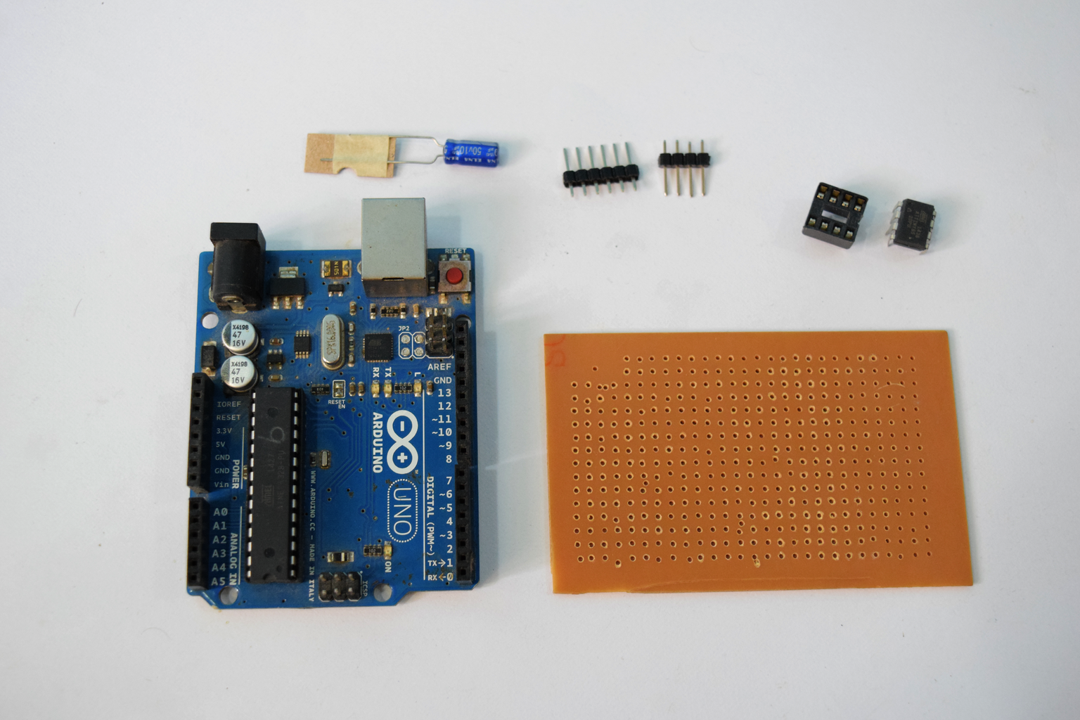
Here is a list of the components and tools required, the list is simple and all you need is
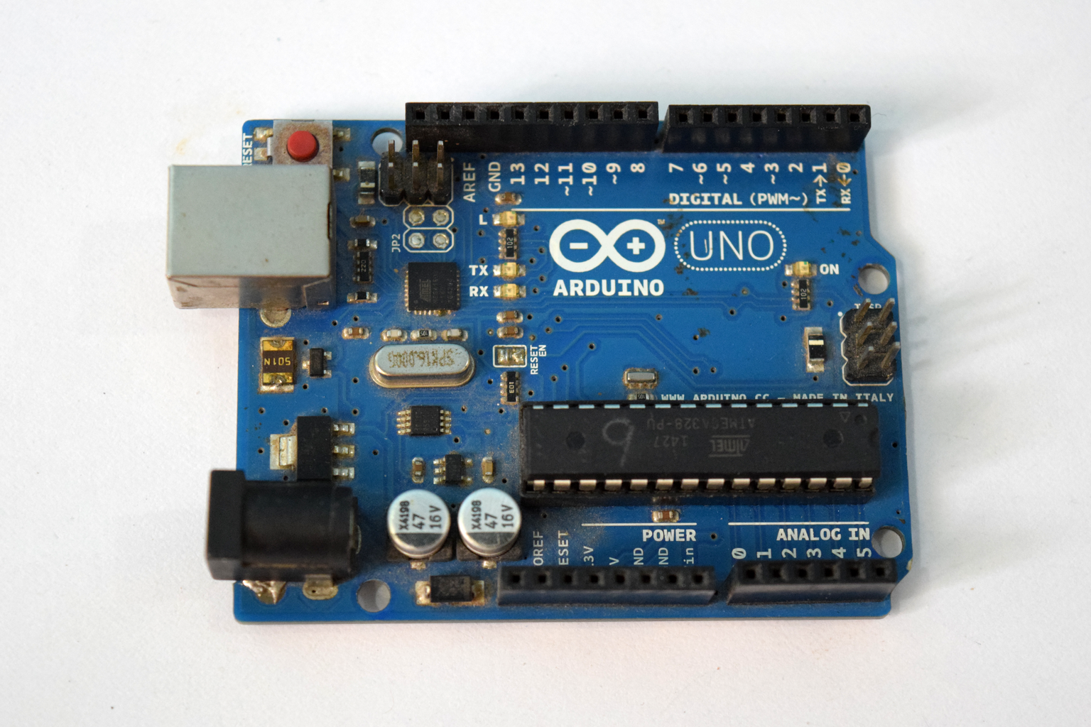
- Arduino Uno
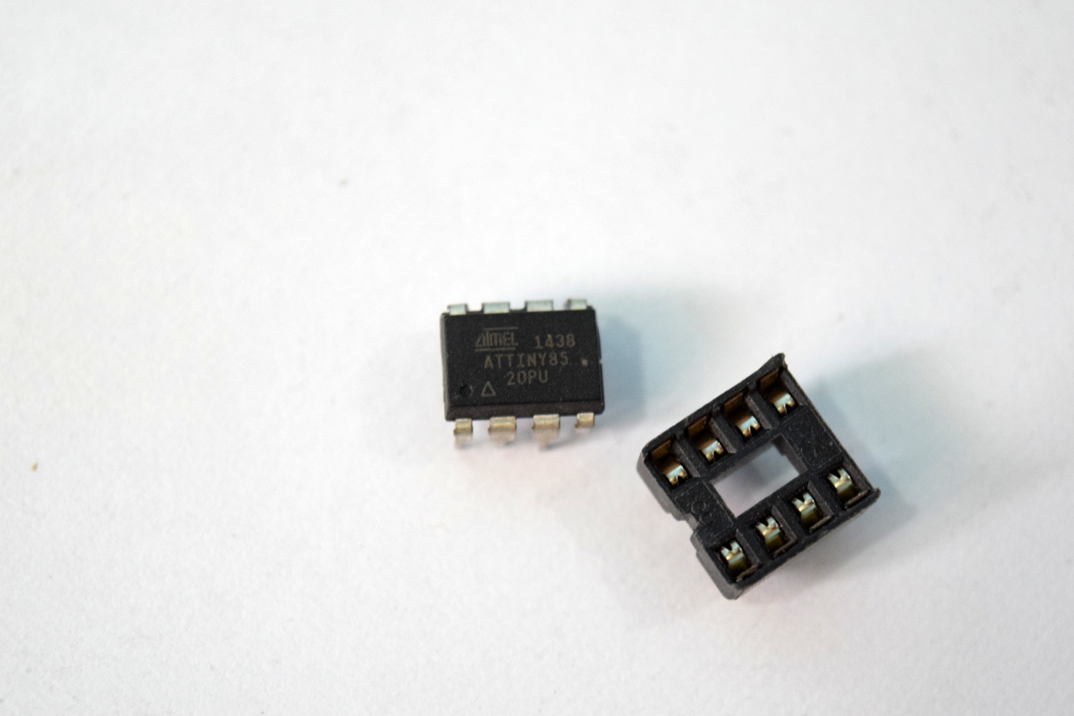
- Attiny 85
- PCB
- 10uF Capacitor
- Header Pins
- Wires
- Soldering Iron
- Soldering wire
Step 2: Measuring

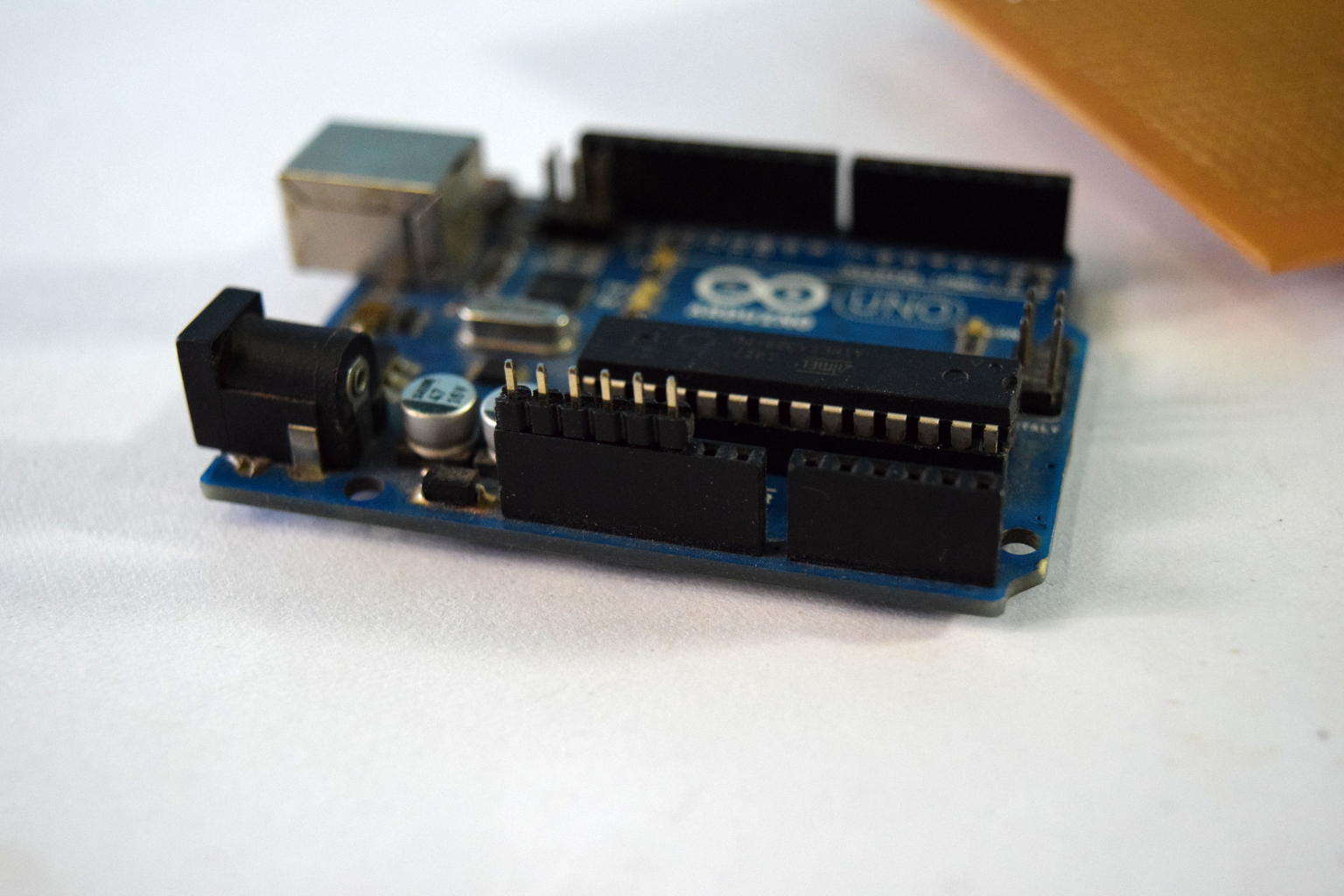
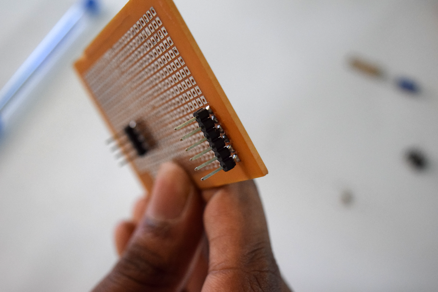
For this project we will be using the digital pins 10, 11, 12, 13 and the +5v, Ground and Reset pins of the arduino uno. So lets start with cutting out the header pins to the required amount. Then plug the headers into the PCB and mark the layout of the shield. Solder the header pins on to the Arduino, to solder the pins move the black connectors up a little bit and then solder it.
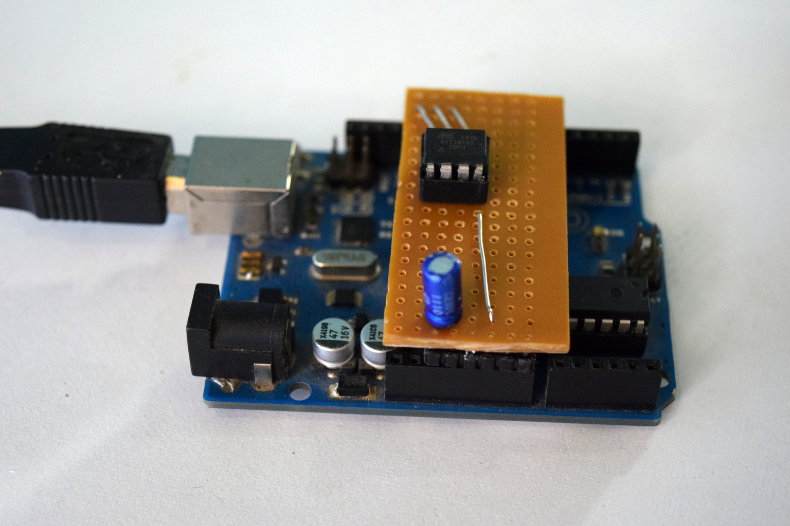
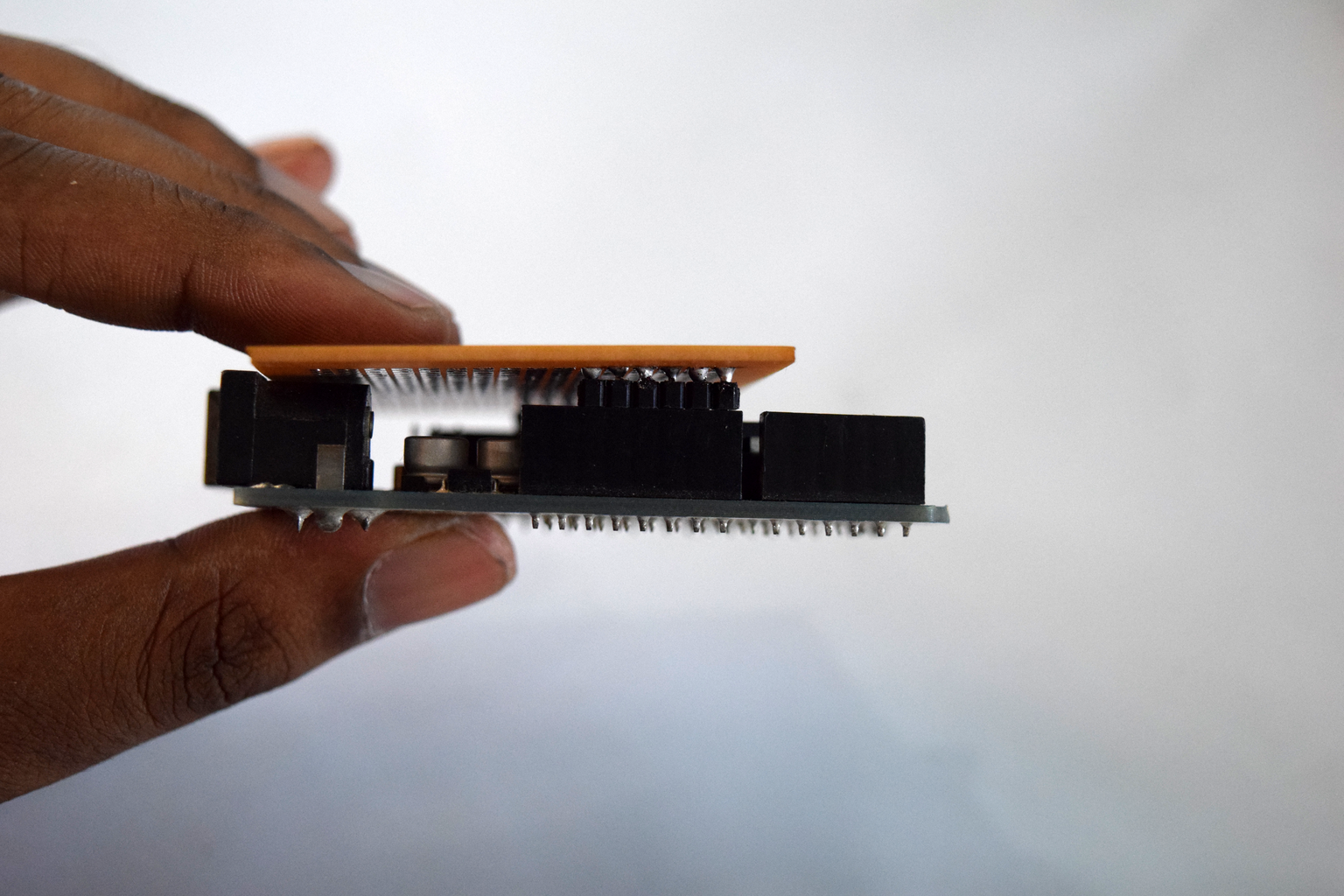
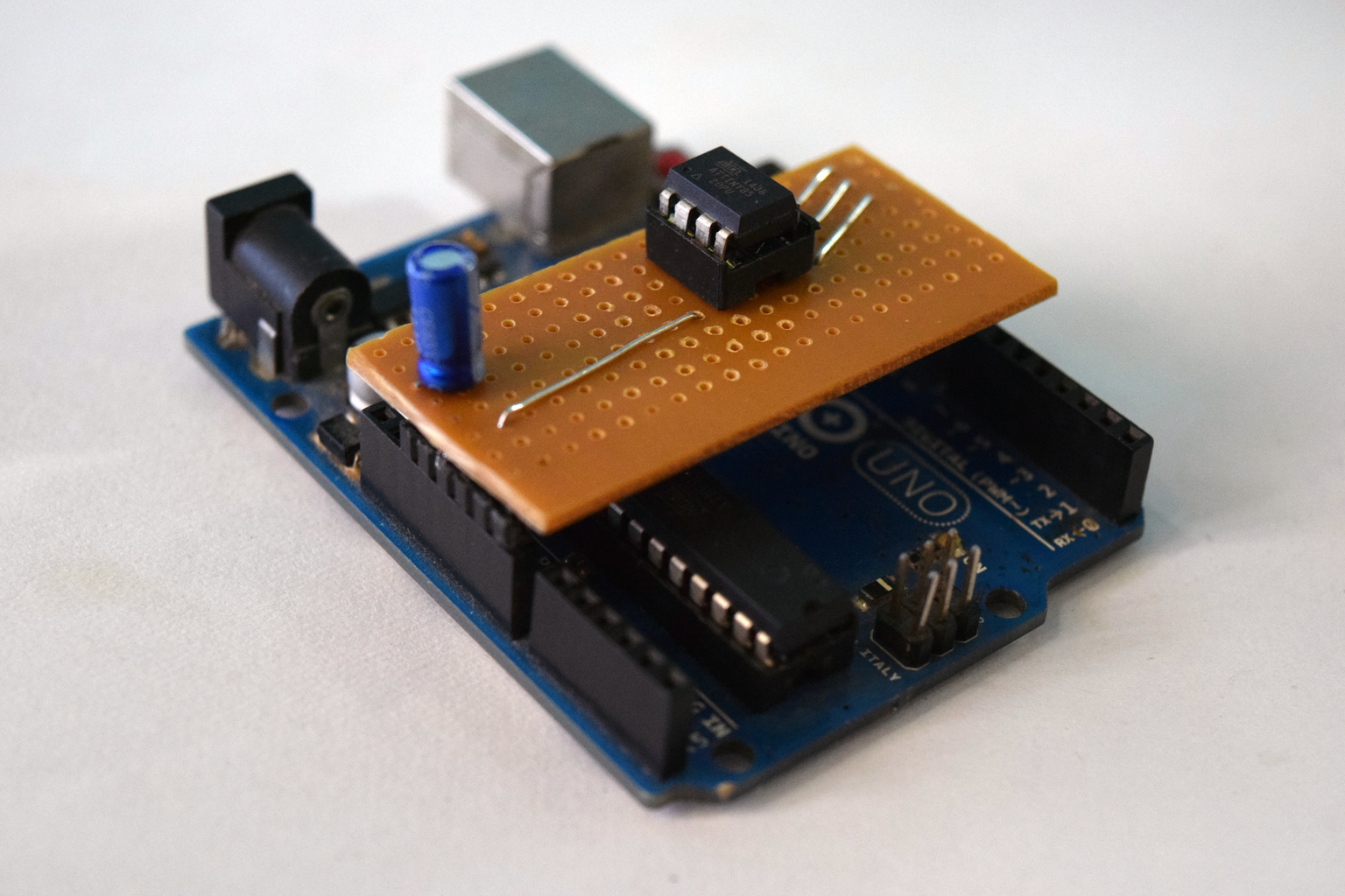
After soldering place the PCB on the Arduino to see if everything fits fine.
Step 3: Cutting
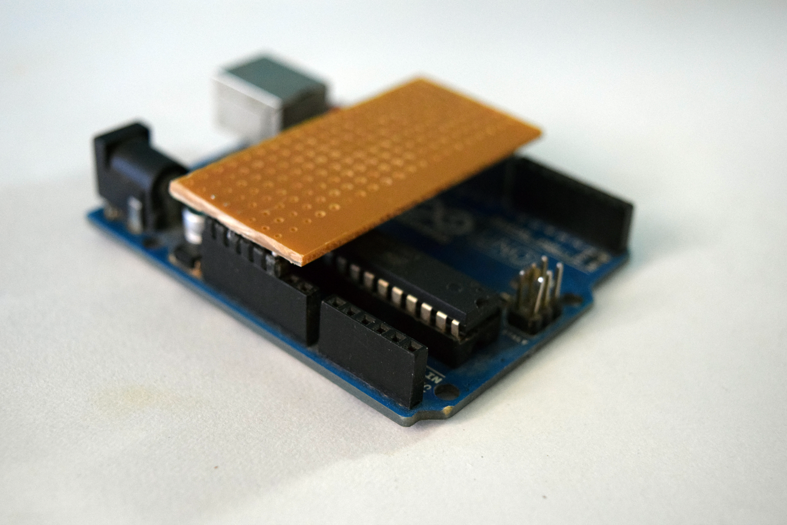
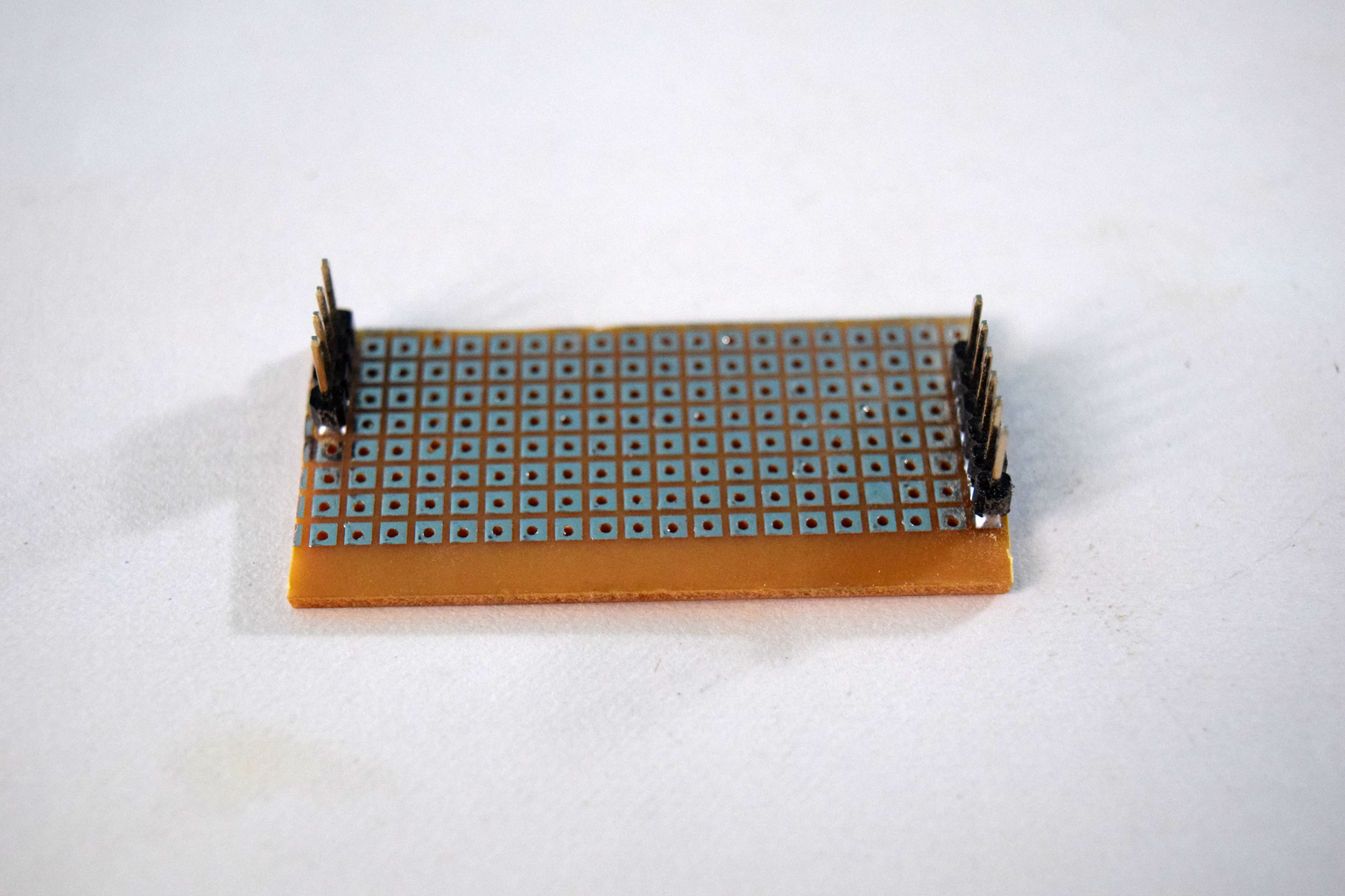
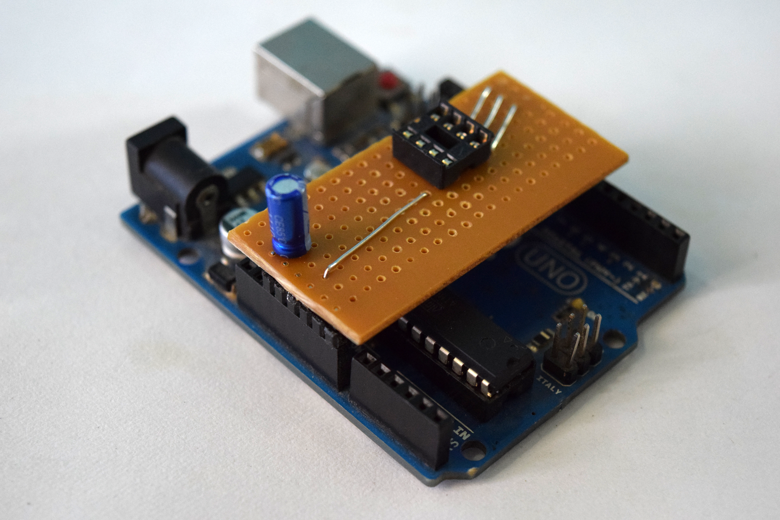
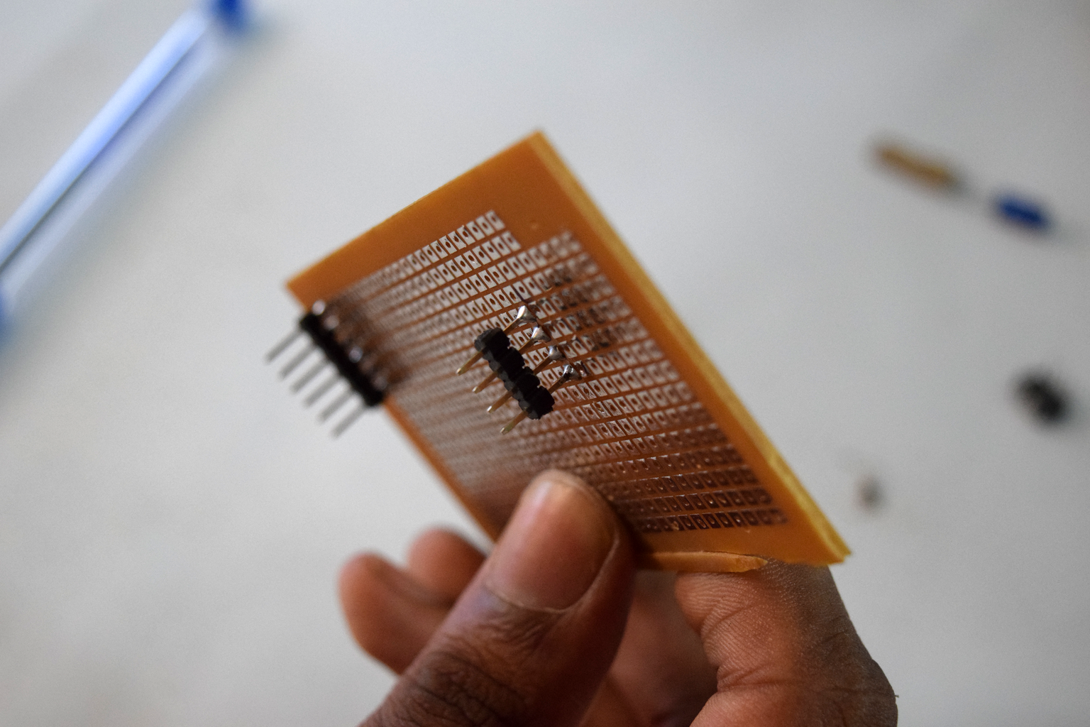
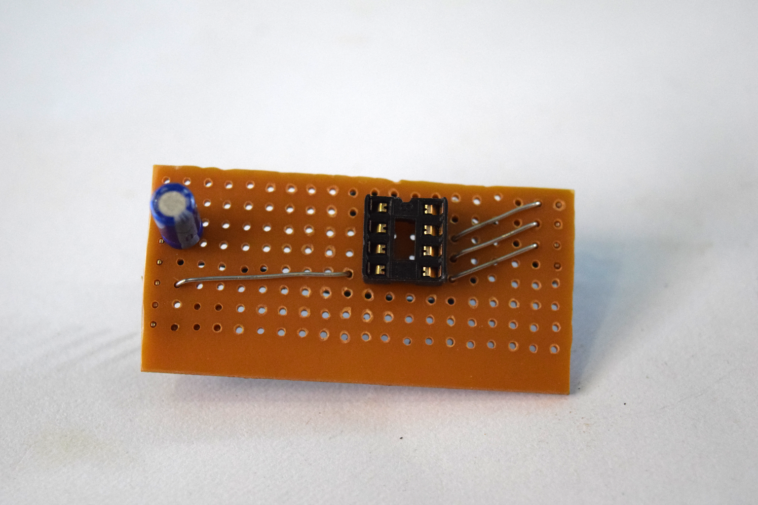
After soldering the headers lets cut the excess PCB out, to do this I used a rotary tool, you can also use a PCB cutter. Make sure you leave enough space for the attiny IC and a few connecting wires. After cutting the PCB you should have a shield, like the one in the picture.
Plug the board on the Arduino to make sure it fits right.
Step 4: Circuit
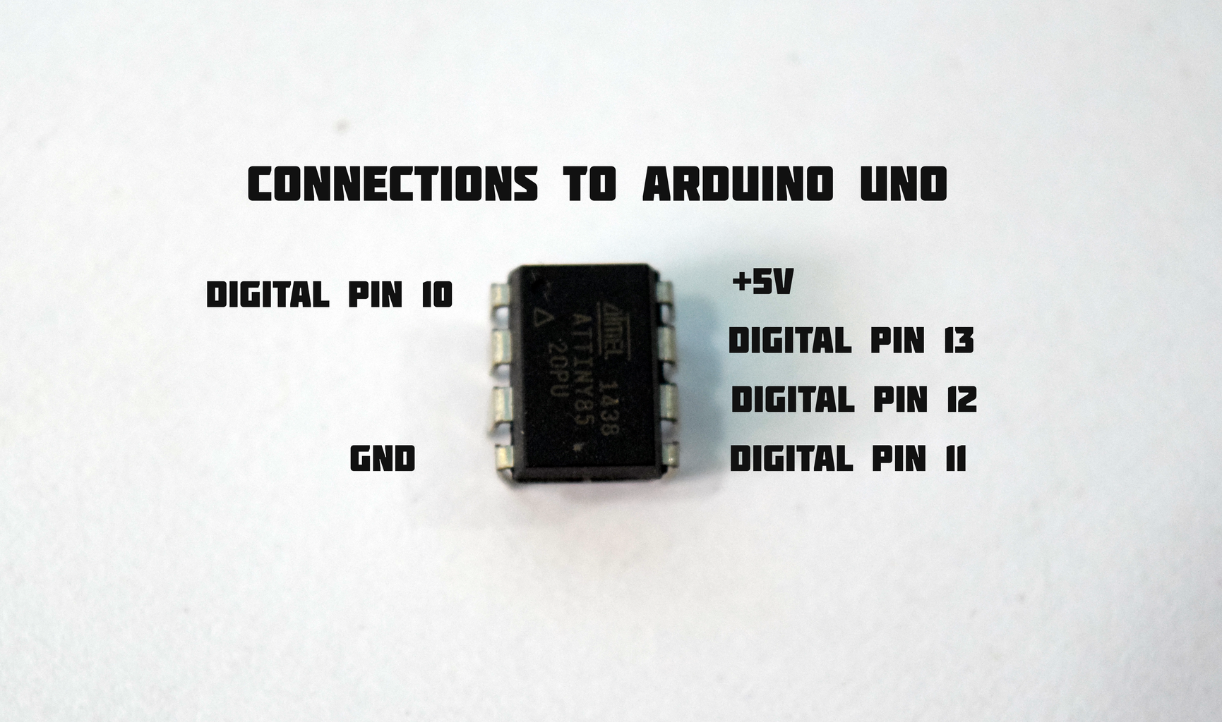
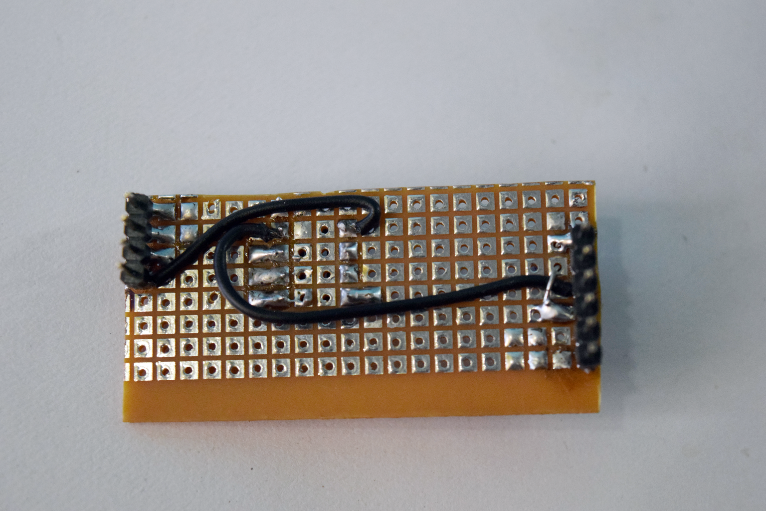
Now it is time to solder the rest of the components, the circuit is fairly simple and the connections goes as follows
- Attiny pin 1 to arduino digital pin 10
- Attiny pin 4 to arduino Gnd
- Attiny pin 5 to arduino digital pin 11
- Attiny pin 6 to arduino digital pin 12
- Attiny pin 7 to arduino digital pin 13
- Attiny pin 8 to arduino +5V
You also need to add an Capacitor across the the reset pin and the Gnd pin of the Arduino.
Step 5: Arduino IDE
Now that the circuit part is done, the attiny is ready to be programmed, for this you need to install a plugin to the standard Arduino IDE. In the arduino IDE, navigate to File=> Preferences now add the url in the column.
https://raw.githubusercontent.com/damellis/attiny/ide-1.6.x-boards-manager/package_damellis_attiny_index.json
Next, navigate to the boards manager and install the attiny package. Now you should see the attiny tiny board in the list of boards. Now you can program the attiny by selecting the right port.

Participated in the
Makerspace Contest


