

Introduction: Arduino-Based Handheld Simon Game


About Me
This Instructable was written for the Instructables Game Design competition in Spring of 2023. I am Christopher. I run Christopher's Factory, where I make a lot of videos, instructional material, and projects aimed to inspire others to learn new skills, especially skills they might otherwise view as being out of their reach. I am a Senior at Texas State University, where I study finance. This discrepancy between what my hobbies are and what I study in school is a big inspiration for my channels' content. I am not trained in electronics, engineering, physics, or anything even related to STEM -- but I am a firm believer that in the modern age, anyone can learn any skill, it's simply a function of dedication and willingness to learn new things.
You can find my tech, Arduino, 3D printing, and DIY wind turbine content on every major social media platform under my handle Christopher's Factory (@christophersfactory), and you can contact me via email at christophersfactory@gmail.com.
About This Project
Simon is a short-term memory game. The beautiful simplicity of the game makes it an entertaining pastime for all ages, as well as a commonly referenced example project in the fields of programming, electrical engineering, and product design. This project will combine several broad skills concepts that are common to makers. If you're worried your skills may not be up to par, fear not! I will break everything down as simply as possible while providing checkpoints along the way, as well as finished files, schematics, and code for those who are more interested in just making the game than learning the theory.
As a little bit of lore, I programmed a software version of Simon for my 7th grade science fair project. I made several versions of the game, which progressively incorporated more senses of the human body. The most sensory deprived version had a monochrome and monotone design, with all of the buttons laid out in a 1x4 line instead of in a 2x2 square. I had as many people as possible test different versions of the game, and aggregated their score data to back the hypothesis that short-term memory was greatly improved proportionally to the number of senses involved in creating the memory. Because of this connection to the game, I was excited to re-imagine it in a whole new way, especially as a physical game rather than a poorly-coded program.
This Instructable is written such that anyone, even with no experience at all, can follow and understand every step. Those at a higher skill level should skip through, taking the files and resources they need. Code, Fusion 360 models, and resources can be found at the end of each step, and all resources from all steps are cumulated at the end of the project.
Supplies


This guide will be designed to encompass as many skill levels as possible. Those who are adept in the skills necessary will be able to breeze through this guide, cherry-picking the necessary files and resources. Those who are beginners -- fear not! I will explain everything in simple terms. Part of what I think draws a lot of people to my channels is the fact that because I am not an engineer, I think I do better at explaining complex topics in a way that non-engineers can easily grasp.
The reason I say this in the supplies section of this guide is because I don't want you to feel daunted by supplies that may sound complex or complicated. Additionally, the bill of materials may seem long, but many of the components are fairly generic, and the bulk of them can be found in your favorite Arduino or other electronics starter kit. This is the one I learned electronics with, it's pretty comprehensive and I consider it to be one of the most impactful purchases I have made in my entire life (Link).
Lastly, I will link the exact materials that I used for this project, but many of them can be substituted for equivalents. Feel free to look around and see if there is anything you'd rather use. This project will have a plethora of materials provided to make it as easy as possible to adapt the project to your specific needs and component choices.
You will need...
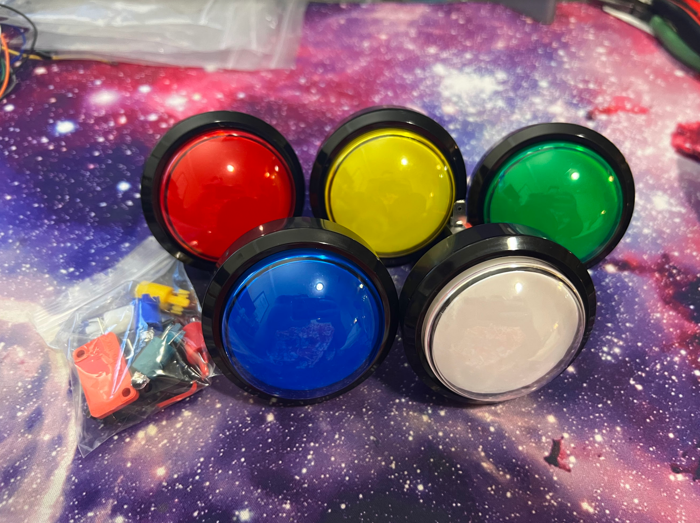
- 4x 60mm LED Arcade Buttons (Link)
- 1x Arduino Nano (Link)
- 1x small speaker, or a passive buzzer (Link) (Link)
- I used a buzzer, I found it to be loud enough. Thus, the project enclosure is designed to fit these buzzers.
- 1x SN74LS32n Quadruple 2-Input OR Gate IC (Link)
- 4x 2n222 Transistors (Link)
- A few different values of resistors, I recommend buying a resistor kit (Link)
- 1/4 Watt resistors will be fine for this project, but it's not that much more for the 1/2 Watt variant, and you may find that more useful for future projects
- Access to Fusion 360
- PLA Filament (Link)
- I linked my personal favorite brand, eSUN. I use their PLA+ almost exclusively, because it's stronger, more durable, and less subject to warping. You don't have to use this specific type, I just find that it goes longer because you can get away with using less.
- 1x toggle switch, I used an MTS-102 (Link)
- 1x DC Barrel Jack (Link)
- Optional if you only want to use battery power
- 1x 12v Wall Adapter (Link) I buy several at a time to save money, they're very useful
- Optional if you only want to use battery power
- 1x 9v battery
- Optional if you only want to use wall power
- Will also need a holder (Link)
Step 1: Coding

Please note that for this step, it is not necessary you do any coding on your own if you do not desire. I have provided my code for you to use or adapt if you'd like.
A Brief Recap of Using Arduino
The Arduino IDE is programmed by using a language that is technically distinct from, but very closely related to C++. For the scope of this project, there are only a handful of functions you'll really need to use, and I'll go over them here.
The most barebones Arduino program is required to have, at the very least, these two functions: setup and loop. Most hardware applications resemble this same basic structure, where there is a set of instructions to be performed once upon "awakening," and another set of instructions to be performed on repeat continuously for as long as the device remains powered. When you open a blank sketch in the Arduino IDE, the functions are already in the code for you, declared as void setup() and void loop(). The void prefix is to indicate that the functions aren't meant to report back with a certain response or anything, they just need to perform the instructions contained therein.
An empty setup and loop aren't very useful -- it's putting commands inside the setup and loop, as well as making your own functions and subroutines that give an Arduino its purpose. Since none of the functions I use in this project will need to return any information, they will all be declared as "void functionname()"
Arduinos have many input and output (IO) pins, and these pins can be used to write and receive data. They can also be used to turn power on and off, by either raising or lowering the voltage on the pin. You may have heard people say that computers work using zeros and ones. In application, what this means is that computers communicate by reading a voltage, and determining whether or not the voltage is above a set threshold, which is called the logic level. The Arduino Nano's logic level is 5 volts, so if you had a 5V battery and applied it to pin number nine, and told the Arduino to read that pin, it would respond with 1, HIGH, or True, depending on the context. These three responses are all conceptually the same thing, which response is used or given simply depends on the context.
Ones and zeros, binary, HIGH and LOW, True and False are all associated withdigital logic. All IO pins can be used for digital purposes, but there is a special set of pins that can be used for analog logic. Analog logic is beyond the scope of this project -- all you need to know about it is that while nearly all the IO pins can be used for digital functions, only the pins specified as analog pins can be used for analog logic.
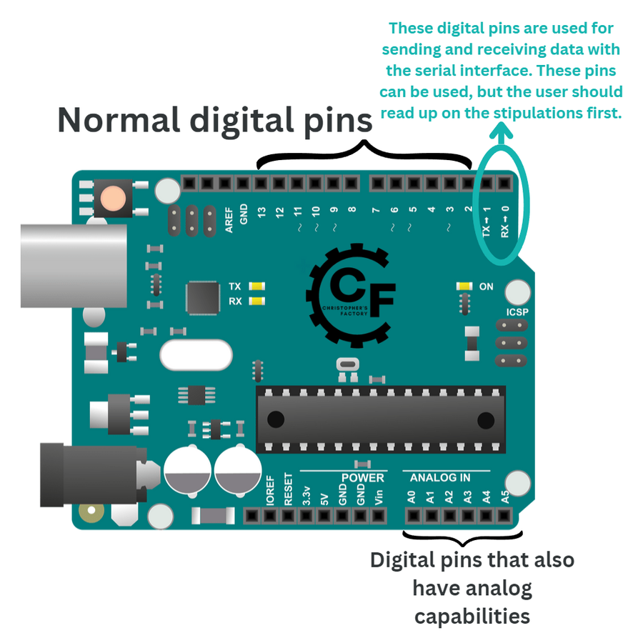
(I used an Uno for this drawing but I am using a Nano for my project. The concepts are the same between the two)
Let's review the syntax and application of the basic functions that will comprise the majority of the code.
- pinMode(pin, INPUT/OUTPUT): tells the Arduino what the pin will be used for. Arduinos can handle a lot, but will always work better when they know what to expect.
- digitalRead(pin): returns an answer of either a 0 or a 1, based on the voltage currently applied to the pin.
- digitalWrite(pin, LOW/HIGH): Applies either 0V or 5V to the pin. This can be used for communicating with other components, or for powering low-current components like the LEDs we'll be using.
- tone(pin, frequency): Used to play a note on a speaker or buzzer. Frequencies are input as integers, measured by hertz.
- noTone(pin): Stops playing any notes on the pin.
- delay(ms): The Arduino cracks a digital beer and does nothing for a time, measured in milliseconds.
Loops
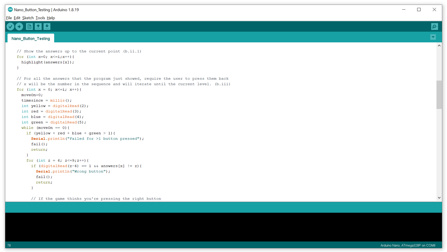
Loops have highly variable complexity. There are super simple loops, and very intricate loops. Rather than trying to explain them conceptually, I think it'd be easier to show an example of one and elaborate on the syntax.
for (int i = 0; i < 100; i++) {
  Serial.println(i);
}
I'll describe what this loop does by describing the thought process that a human might use:
"For every integer, which we will call i, starting from i = 0 and incrementing by one (i++) as long as i is less than 100, display the value of i."
You can probably imagine the output of this function. The program creates an integer variable called i, and sets the value in that variable to zero. The function then prints the value of i (which is zero) to the serial monitor. Then, the function has reached the end of the instructions for that iteration, and adds one to the variable i, as instructed by the loop declaration. It then prints that value (now 1), and repeats this process so long as i < 100.
The full output of this function will therefore be every integer between 0 and 99 inclusive. The number 100 will never be printed to the output. Why? After printing 99, the function will compute 99 + 1 = 100, and it will review the parameters of the for function, and because 100 is not less than 100, it will not perform the commands within the loop, and will instead move on.
Similarly, the while loop performs the commands in the function so long as the input conditions are true. Consider the following code:
continue = 0;
while (continue == 0){
  if(digitalRead(7) == 1){
    continue = 1;
  }

  delay(50);
}

Serial.println("You must've pressed the button!");
Now we're getting somewhere! You've just read your first nested loop, simply: a loop inside of a loop. Here's how this one might be read by a human:
"Continue is a variable with a value of zero in it. As long as continue is equal to zero, read digital pin 7, and if the voltage is ever at 5 volts, change the variable continue to 1. Every time the digitalRead is completed (regardless of the reading), wait 50 milliseconds before going on."
The program will continually check pin 7 and then delay 50ms. If pin 7 is ever high (at 5v), the program will set the variable called continue to 1, and when that happens, the while loop will be broken and the program will move on upon finishing the current iteration.
Alright! I genuinely think this is the most conceptually difficult part of this project, so if you're still on board at this point, I have 2 things to tell you:
- You're doing great
- The worst part is over
One can easily got lost with nested loops, so I like to write a hierarchy for myself in human language, so I can understand conceptually what the loops will need to do in what order. Here is what I wrote for myself before I started coding, so that I knew what the program would have to do in what order.
Setup
- Declare the pin modes
- Start the serial monitor
Loop
- Make a random list of 20 items
- For each of the (i) items in the list
- Run through (x) items up to i, and for each of those x items,
- Light the corresponding LED and play the corresponding frequency on the speaker
- For each of the x items,
- Start a timer
- Read all the buttons
- If >1 buttons are pressed, fail
- If the button is pressed that shouldn't be, fail
- If the timer runs out, fail
- If the right button is pressed, pass
After that, it's just a matter of setting up the loops according to your plan and testing everything out to ensure it runs smoothly.

Step 2: Connections


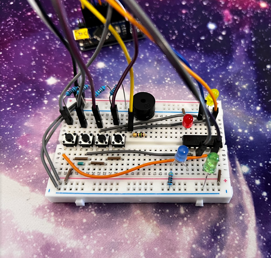
I would recommend you put the project together on a breadboard first so that you can get an idea of what connections go where. It also helps to troubleshoot issues more efficiently.
Here is a pinout list, based off my code, to remind you what connections go where:
Digital pins:
- Yellow Button
- Red Button
- Blue Button
- Green Button
- Yellow LED OR gate input A
- Red LED OR gate input A
- Blue LED OR gate input A
- Green LED OR gate input A
- Speaker / Buzzer
Here's what the project looked like when I was prototyping it on a breadboard. Refer back to this in the rest of the section when I'm describing how things should be hooked up to each other.
Wiring a Button
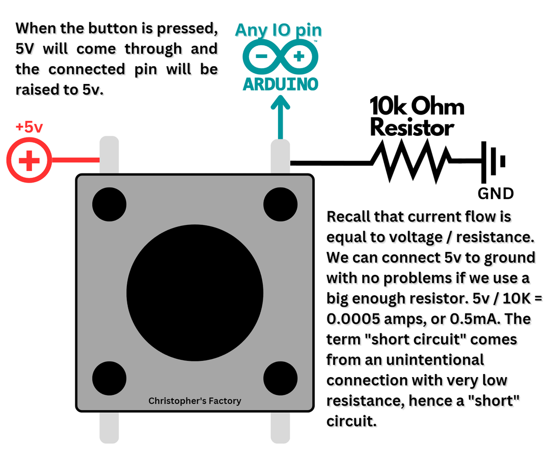
Most buttons do nothing more than close a connection, connecting the circuit. Remember that digitalRead will read the voltage currently on the pin, so it's important to wire your button such that when the button is not pressed, the pin is connected to ground, and when the button is pressed, a flood of 5 volts comes through the button to raise the voltage of the pin. Additionally, we'll incorporate a resistor between the pin and ground to ensure that when the button is pressed, we're not just shorting an unlimited amount of current down to ground.
Some of the most commonly used buttons for prototyping are these little breadboard tactile momentary switches. This is a fancy way to say breadboard button. In the pictures for this step, I included some guides on how these buttons work. The concept is the same for any switch -- 5V on one side, input pin on the other side, as well as a resistor to ground.


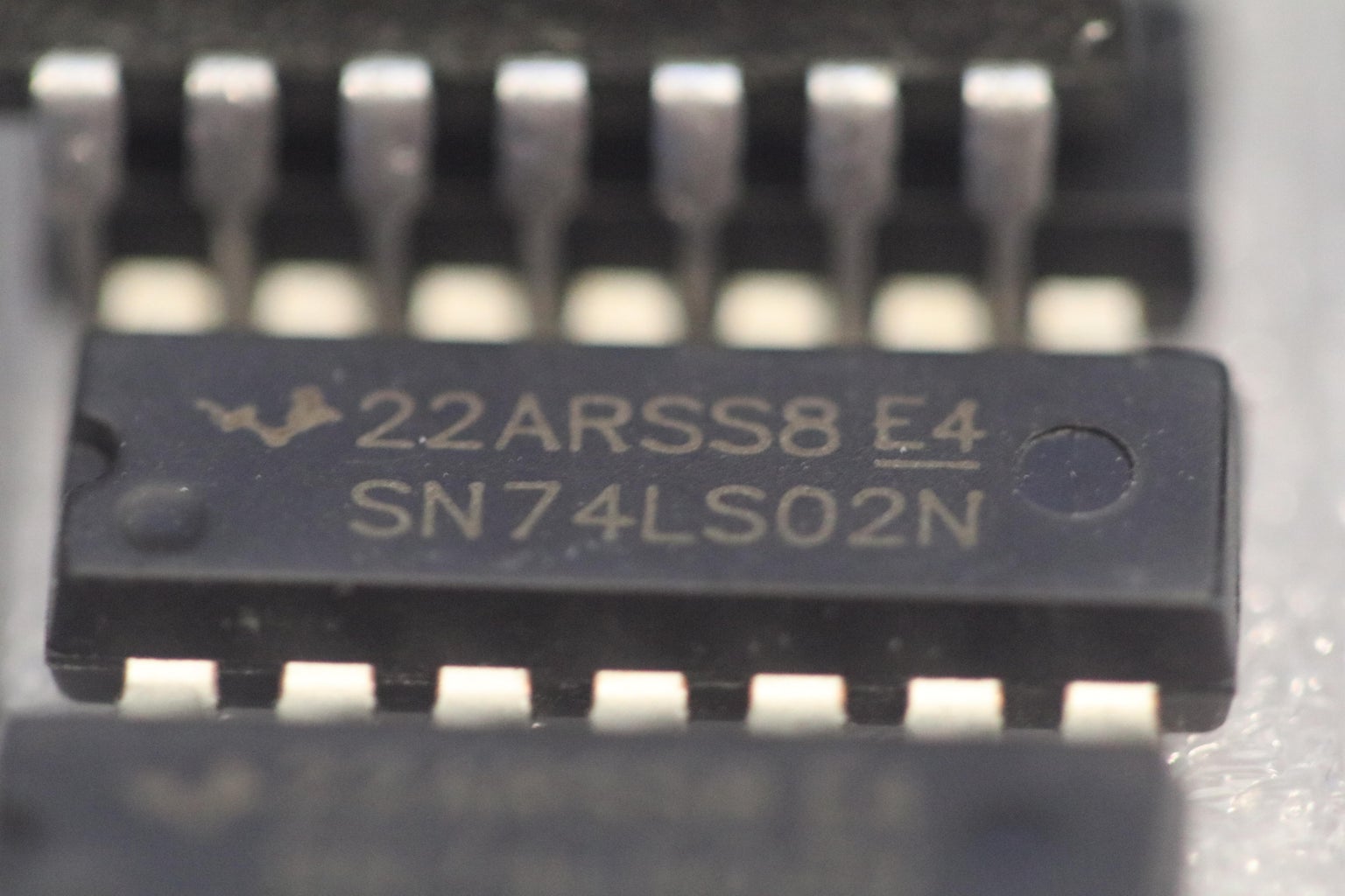
Around this point in any project is when I start making firm design decisions. One decision I made for my project is that I wanted the LEDs to light up any time the Arduino sent a signal, but I also wanted them to light up any time the user pressed that LED's button, regardless of whether the Arduino was expecting the user to press a button or not. To make this easier, I implemented a SN74LS32n chip, which is an integrated circuit that has four OR gates on one package.
(I know someone is going to say, "Couldn't you have just done this in software?" to which I say yes, but I didn't want to. I felt like using an IC would have been a good transition for beginners into more intermediate electronics, and it simplified the coding, which many people find to be daunting.)
What that means for the project is that the LEDs will be controlled by a small, 14-pin IC package. The IC has four sets of 3-pin OR gates, and each of the 3-pin sets has two inputs and one output. If either input of a gate is raised to 5v, the chip will raise the output of that gate to 5v and allow current to flow through.
In the picture below, you'll see what is called a truth table. This truth table describes the behavior of a two-input OR gate, like the ones inside the IC. You can see that if either A or B is 1 (meaning raised to 5v), the output will be 1, meaning raised to 5v).

Each Y will be hooked up to the positive end of an LED. While prototyping on a breadboard, I did not use resistors because the IC only outputs ~15mA, which is about right for most LEDs. The LEDs of the buttons I will be using already have built-in resistors inside them. Recall that through Ohm's Law, voltage, current, and resistance are all related. Power is measured in watts, and combines voltage and current by multiplying them. LEDs are generally rated for a maximum power. This means that you can generally have either a low voltage and a high current, or a high voltage and a low current, and as long as the power doesn't exceed what power the LED can handle, it will be fine.
The button manufacturer said to use 12v. Anything less than that will dim them, and anything more than that might burn them out. After probing the LED assembly with my multimeter, I found that there was a 460 ohm resistor put in series with one of the legs. There are two things one could do in this situation:
- Gut the LED and replace the resistor with one of a lower value
- Change the LED's power setup
I decided I didn't want those following along to have mess with the internals of the button, so rather than powering our LEDs directly from the OR gate IC, I'm going to have the 5v output of the IC toggle a 12v circuit by implementing a transistor. Transistors are awesome. They have tons of uses, but for the scope of this project, you can think of it like a switch that is toggled by an electrical input rather than your hand. Through this, we can have the switch toggle a 12v connection when it is given a 5v input signal. How cool is that?
I find the naming convention of transistors' pins a bit tough to conceptualize, so here's a sample circuit instead that I made to illustrate how one would use a transistor in a typical application.
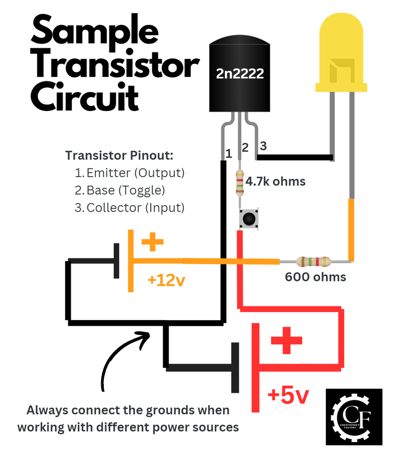
As you can see, the transmitter works by completing the 12v circuit, allowing the LED to connect to ground when the middle pin is raised to 5v. We add a 4.7k resistor to ensure power from the 5v source isn't being wasted, since it only requires a very small amount of current to toggle the transistor. An important note -- this is a usage schematic for a 2n2222 transistor. There is another common transistor, the BC547A, that has the emitter and collector pins swapped. One can remember the transistor's confusing terminology by thinking of the collector as collecting electrons, and the emitter emitting them out.
So now we have the power issue sorted out. We can have the Arduino write 5v to a pin, which will then toggle a transistor, which then completes the 12v circuit, turning on the lights. This obviously raises the question, though -- what will be the power source for our handheld Simon game?
Step 3: Power


Conveniently, Arduinos have voltage regulators on them, and all of the 5v logic level Arduinos (Nano, Uno, Mega) have a maximum input voltage of 20v. This is great for us, because whatever 12v power source we use to light our LEDs can also be fed into the Arduino, and the Arduino will regulate that down to the 5v that it needs to operate.
So where shall we get our 12v power source? There are a couple things we could do:
- Connect 8 AA batteries together in series
- Connect 3x 18650 LiPO batteries in series, which might be nice because they're rechargeable
- Use less batteries, but implement a DC-DC voltage boost converter to raise the voltage up to what we need
- Use a single 9v battery and be content with the LEDs being dimmer
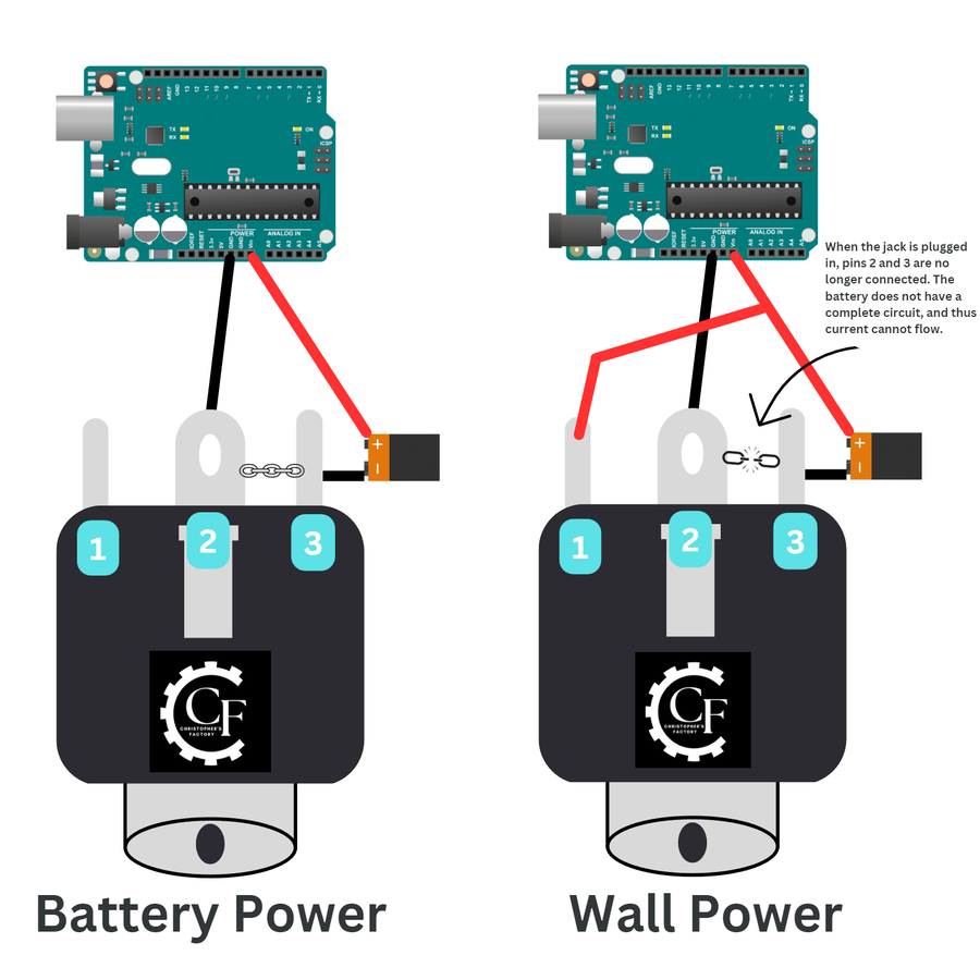
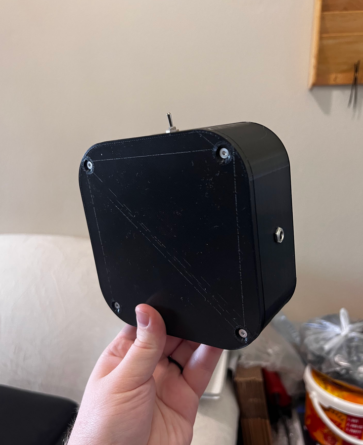
All of these options would work... A single 9v battery is the easiest option, but it will probably need to be replaced after a few hours, but that's fine for me, as I don't think it's likely I'll be playing this constantly. We'll add a barrel jack to the enclosure so that the game can be plugged in the wall if the batteries are dead and you can't be bothered to go to the store. One thing I absolutely love about the barrel jacks I linked is that they have an internal switch that can be used to disconnect a battery circuit when the barrel jack is plugged in. This ensures that no battery power is wasted as long as the game is plugged in.
We're also going to add a toggle switch on the side of the box that disconnects the ground of all power sources (wall and battery) when switched. When using precious battery power, every little trickle of power becomes crucial, so it's important to erase any possibility that power will be used. Plus, I think that starving an Arduino of power is, by far, the easiest way to turn it off. No latching flip-flop circuits, no deep sleep and wake, just cut the power!

These barrel jacks have a threaded shaft and come with nuts, so we can measure the diameter of the shaft and use the nut to secure it to the enclosure of our project.
I decided while writing this section that in a future project, I want to use an 18650 cell and a boost converter so that it can last longer and be rechargeable. I figured that alone is probably worth its own Instructable, so be sure to follow me here and on other socials if you want to learn how to do that.
Here is the switch that I will be using to turn off the device when not in use:
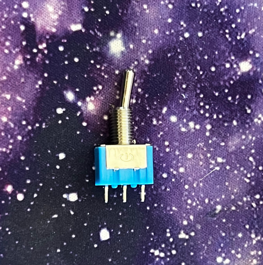
This is a dual pole switch, but we're only going to be using one of the pole sets. These switches can be used for more complicated circuitry, but I'm just going to be using it to open or close a connection, the same function a standard two-pin switch would perform. As such, I'll only use the left and middle pins. Pull the lever will control the continuity between the middle and right pins, disconnecting the circuit, cutting off power, and turning off the Arduino.
So, in terms of hooking everything up, we want the power switch to overrule the switch that's in the barrel jack, so we'll have pin 2 of the barrel jack go to the switch. Recall that pin 2 will either carry ground from pin 3 from the 9v battery if nothing is plugged into the jack, or ground from the wall if the jack is plugged in. Either way, ground must come through pin 2 of the barrel jack to complete the circuit, so I'll make that ground have to also go through two adjacent pins of the switch. This will make it such that no matter if our game is running off battery or wall power, we can still cut off power with this one switch.
Step 4: Modeling an Enclosure in Fusion 360


Take a deep breath and crack yourself a cold sparkling water. Look how far you've come! We're on the home stretch now, and you're close to impressing all of your friends with your Simon game.
As I mentioned in the beginning, this project is my entry for the "Game Design" themed Instructables competition, presented by Autodesk Fusion 360. As such, one of the requirements for the project is that it uses Fusion 360 in the design. For me, it'd be more challenging to have to make a project without Fusion 360! As a maker, Fusion 360 is imperative to all of my projects. It's an incredibly versatile tool -- to the point where I often find myself using it for even basic drawings and sketches because I prefer the intuitive interface.
If you are a student, you can get free access to the full, enterprise-level version of Fusion 360 at this link.
If you are a maker or hobbyist, you can get free access to a slightly limited but still extremely powerful version of Fusion 360 at this link.
Now, let's get to modeling!
The first thing I did is measured everything that would need to go in the enclosure. Then, I sketched a really rough design of what I might want my game to look like. Some people like to plan out every detail of their project before starting, but my preferred modus operandi is to just start running in the first direction I feel like, and then make changes and improvements as I go along.

One of the most powerful tools in Fusion 360 is the timeline, which allows for parametric modeling -- using variables instead of numbers, that way if you want to change the diameter of each of the buttons' holes, for example, you can do so by changing one single term, rather than needing to go through one-by-one and widen the holes.
To access user parameters, go to Modify < Change Parameters < + User Parameter. Then, you can create your variable, define what units it will use, and specify a length, angle, etc.

I added several parameters as I went along to allow myself to tweak the design. I was really glad I did this, because there were several times that I needed to make walls bigger, expand holes, etc., and I was glad I didn't have to go through and do it manually.
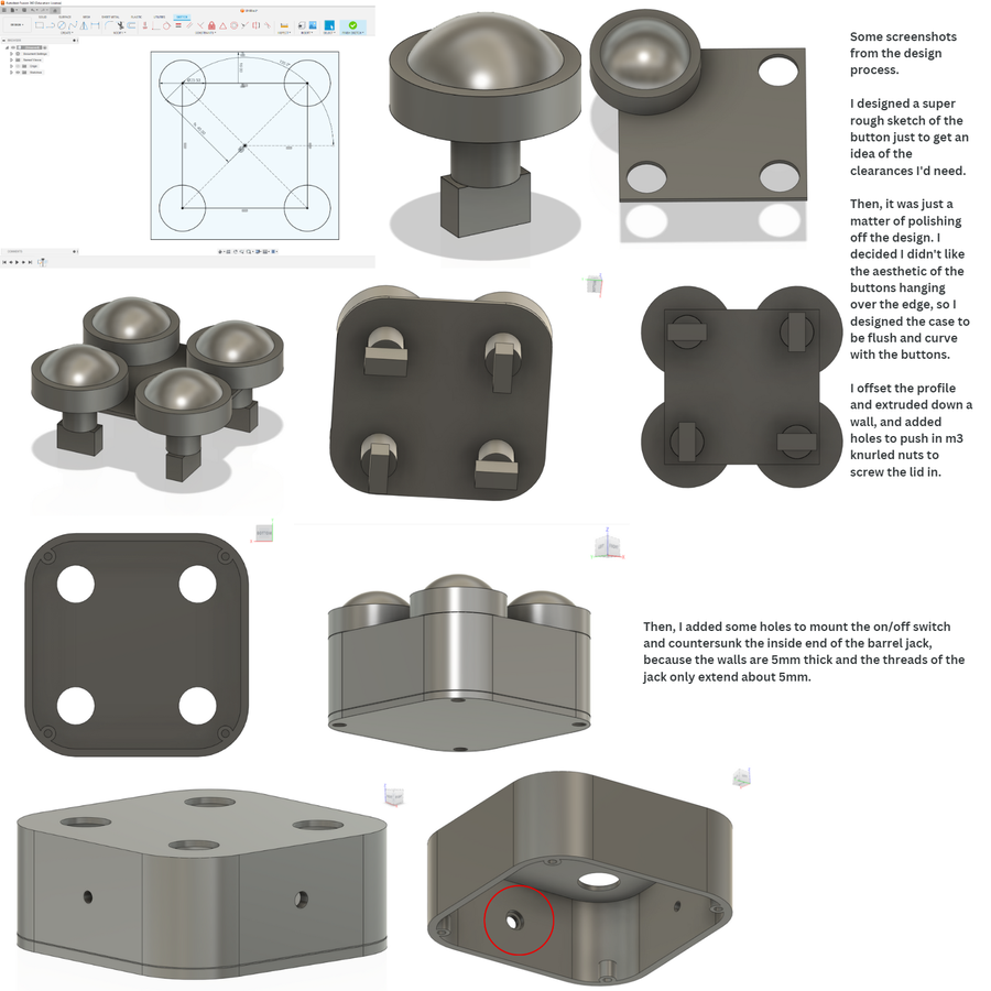
I also added a cylindrical hole to jam the buzzer into (I'll also make a version that fits the speaker that I linked, the shipping was delayed on mine), and printed it on my Ender 5 with supports, 20% infill, and a 0.6mm nozzle and 0.32mm layer height. It took 6.5 hours and 138 grams of filament for the body, and about two hours 50 grams of filament for the lid.
When those parts finish printing, here's your to-do list, roughly in order:
- Remove all supports
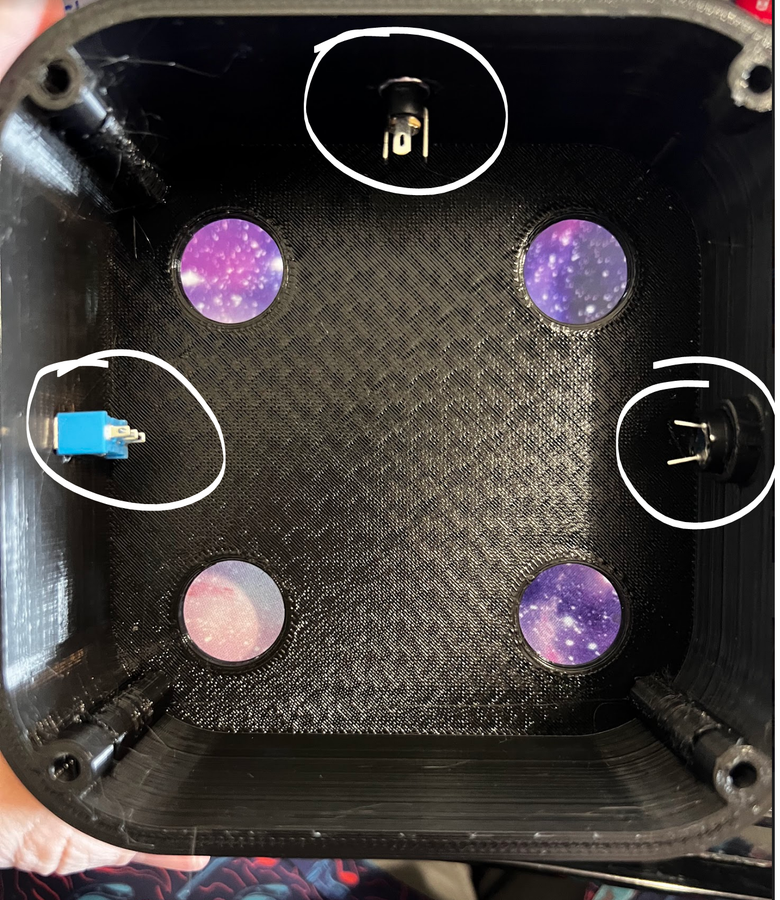
- Put the switch, jack, and buzzer in place. Don't tighten the nuts down yet.
- Solder the knurled nuts in place (more info on this below)
- Gently remove the button internals by twisting counter-clockwise on the red and black rectangle. It will click out of place and can be easily removed. This step is necessary to fit the buttons into the enclosure.
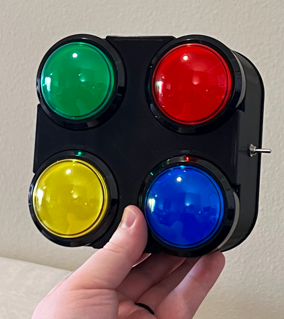
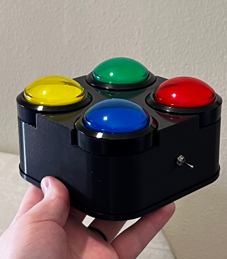
- Put the buttons into their places, ensuring to follow the convention for Simon (example)
- Screw the nuts for the buttons on first, then gently lock the lights back into place
- Tighten everything finger-tight
Here's a video on how to remove the internals. It's not hard, it just helps to see someone else do it:
Here are some pictures from the steps above:

These pictures were all of the V1 box. I decided that the buttons were bulging up too far out of the enclosure too much for my liking, so I made a V2. I also adjusted a few tolerances and made it so that the whole thing can print with only supports touching the build plate.
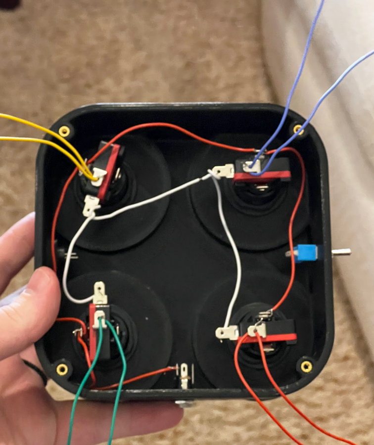
You'll want to probe the LEDs to find the positive and negative on each one. Out of the four I used, I had three where the positive leg of the LED was connected to the pin on the black side of the switch, and one that was the opposite, so you'll want to make a note of the polarities.
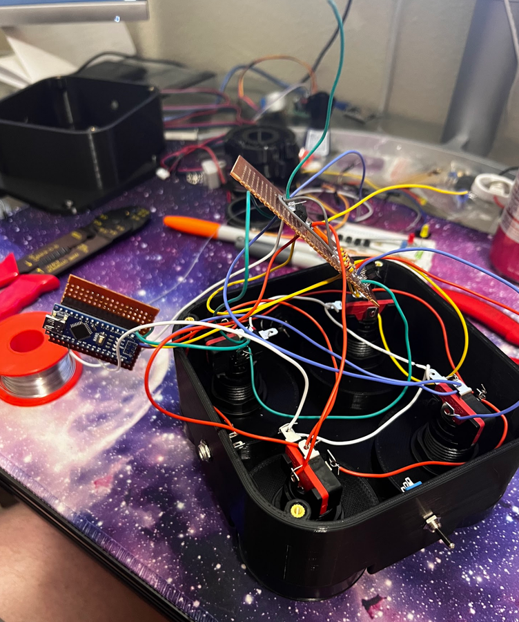
Now, we find ourselves at a crossroads. If you trust yourself, you can put together a piece of protoboard and begin hooking everything up. I will go over how to do that now, but if you want to save yourself some time and the headache of debugging, you can skip to step #5, where I will show how I made a custom printed circuit board to make all the connections easier.
If you're bold and want to wire everything by hand, start by connecting all the 12V legs of the LEDs to each other, to the VIN of the Arduino, and to the positive leg of the DC barrel jack.
Then, pick one of the button pins and connect that pin of each button to one another, then to the 5V pin of the Arduino. Get two wires and connect both of them to the button pin that was not connected to 5v. One of these wires will go to that LED's OR gate, and to the corresponding pin of the Arduino that handles the digitalRead for the button. Ensure that the wire that goes to the Arduino also has a branch that goes to a 10K resistor, and then to ground.
Here is a schematic of how each button needs to be hooked up to the Arduino:

It's not super important if you hook your LEDs up to different pins than the ones I used, but it is important that the Arduino knows which pins are which color, so it can play the correct tone. For this part of the project, I went to my parents' house, dug an old Simon game out of their game closet, changed the batteries, and played it with a tone analyzer app open on my phone. From this, I was able to get the exact tones. There are two sets of tones that Simon used. Some of the original Simon games used a B♭ minor chord, but the more recognizable variant is an A major chord, the notes and frequencies of which are:
Green: E4 (329 Hz)
Red: A3 (220 Hz)
Yellow: C#4 (277 Hz)
Blue: E3 (164 Hz)
For the purposes of this project, these tones may also sound better either shifted up an octave, or in the B♭ minor chord. Totally up to preference. Here's a note chart if you want to play around with other notes and frequencies, here's a chart that will help you connect notes to frequencies.

Then, I started hooking everything up according to the plans

Find the Fusion 360 files and STL files for this step in the supporting files section below.


Step 5: (Optional) Circuit Board

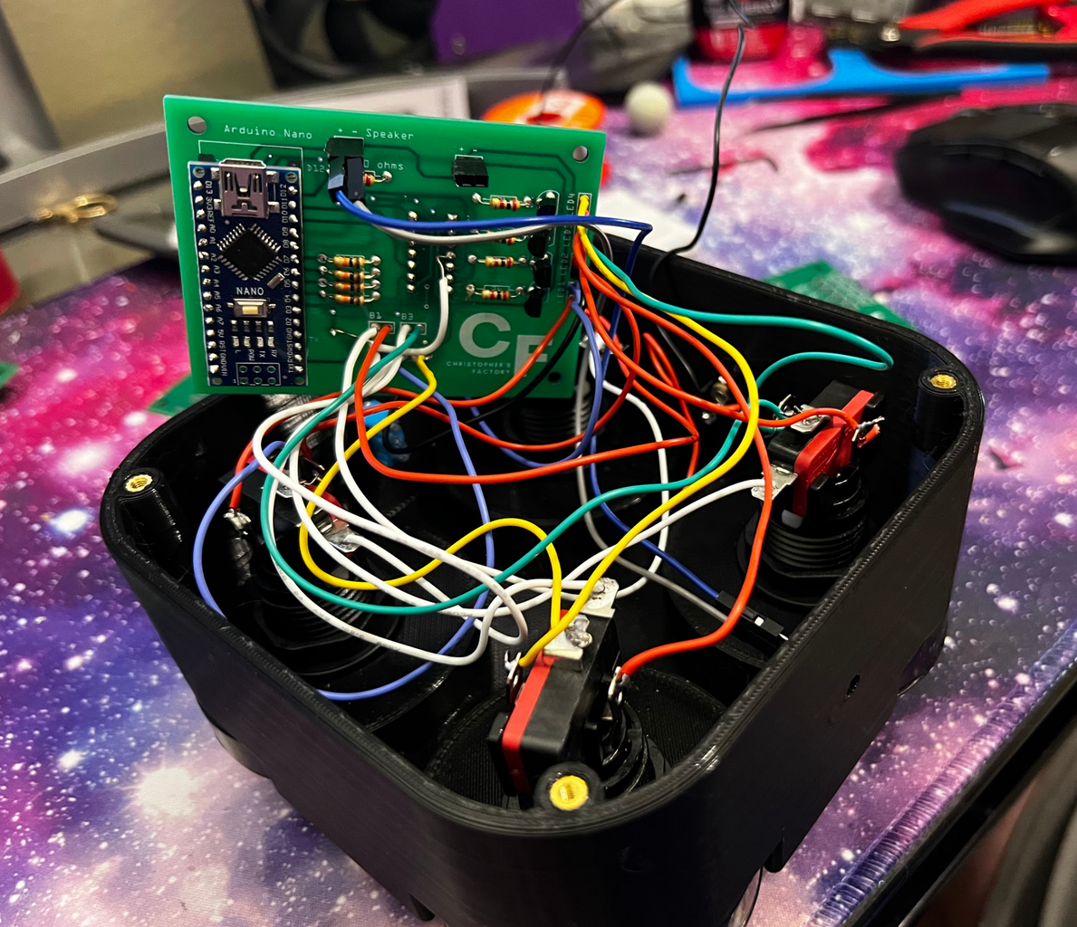

I decided to lay out a circuit board to make all the connections easier. When making my protoboard, I found that I was using tons of excess space in the name of keeping things organized, accidently bridging several connections in the process, and I spent a long time debugging and probing the board for errors. Where custom PCBs were once an expensive luxury of those with the skills and funds to make them, custom PCBs are now a reasonable alternative for hobbyist prototypers. There are several rapid prototyping PCB companies that will make small-batch boards for cheap. I got my first 5 for $0.40 each (shipped), and they were even cheaper after I verified that my design worked properly and I was able to order a larger amount.
Step 5 of this project does not include any new information, but instead is simply a translation of the circuits and schematics from past steps into Fritzing, a program for hobbyists and enthusiasts to easily design simple circuits, diagrams, and PCBs.
I have included the files for my circuit board for free on this project (Link). Readers may use and edit these files for any personal/non-commercial purposes. Since most PCB prototype manufacturing services have a minimum order quantity, I also included headers for the pins unused in this project so that you can repurpose the boards for other projects.
You'll also notice that I try to socket everything when possible, but especially, especially Arduinos. Even if they're cheap, it's still a few dollars that can be saved with minimal effort.
At this point, you're done! It's just a matter of testing all your connections. What I recommend you do from here is play around with the code -- mine was admittedly somewhat hastily written and has many things that could be improved upon. Also, with the same wiring, you could implement a screen, counters, you could make up a new game completely from scratch!
Gerber files for the board are available to download for free on my Patreon (Link)
If you made it to the end of this project, I'm proud of you! I hope you learned something along the way and had fun doing it.
Rather than trying to gatekeep project information and files behind paywalls, I try to keep my work accessible to everyone. That being said, this project took me a surprising number of hours and many days' work, and if you'd like to contribute to my efforts to educate and inspire, it would very much help to keep the lights on in Christopher's Factory. (Paypal Link)

Second Prize in the
Game Design: Student Design Challenge


![Tim's Mechanical Spider Leg [LU9685-20CU]](https://content.instructables.com/FFB/5R4I/LVKZ6G6R/FFB5R4ILVKZ6G6R.png?auto=webp&crop=1.2%3A1&frame=1&width=306)


