

Introduction: Arduino NES
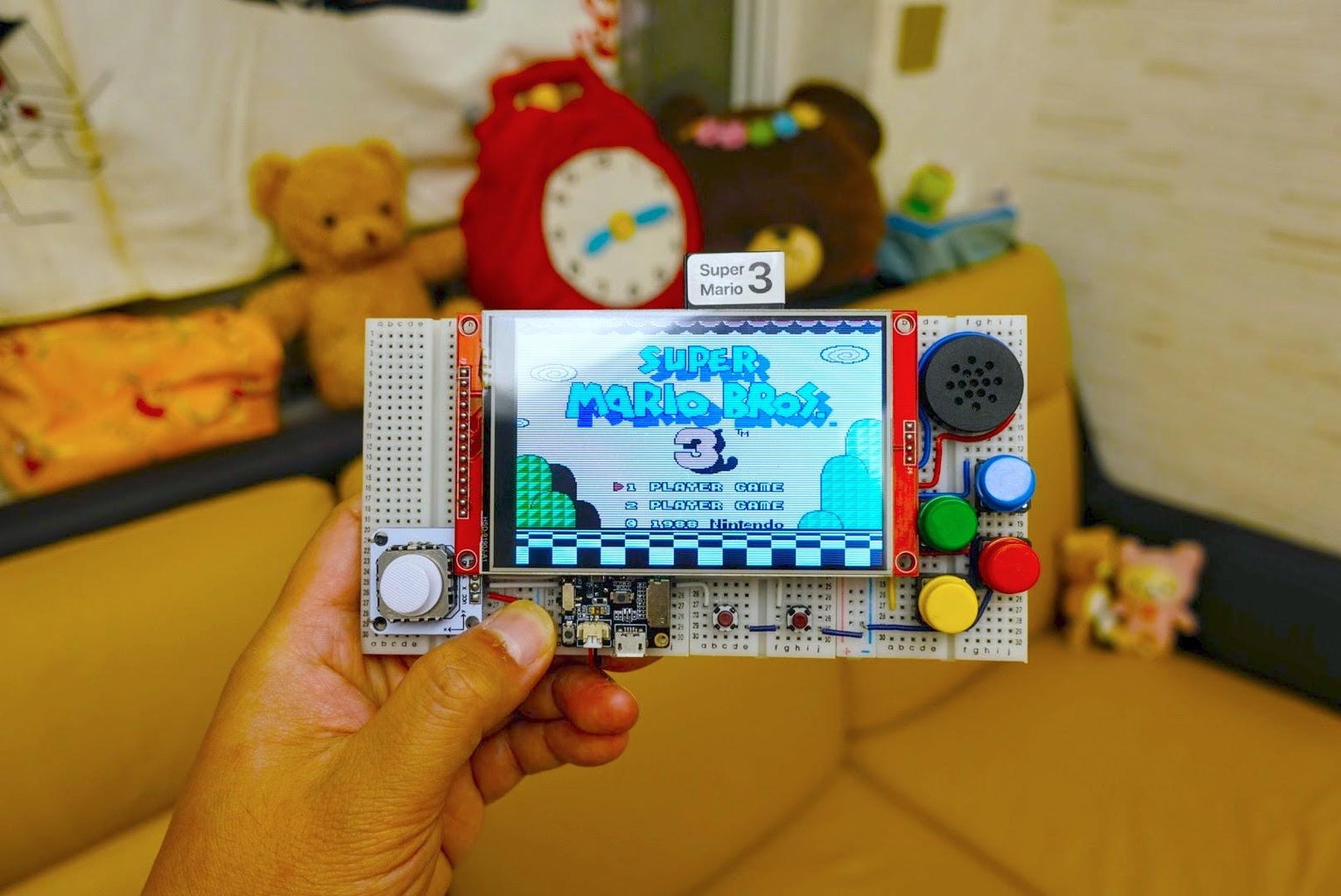


This instructables show how to build a portable NES console with Arduino IDE.
Note:
currently most NES emulator required manual command line build with sort of C compiler, e.g. esp-idf, it is a big barrier for the beginner. I believe make it Arduino IDE compatible can break this barrier, enjoy!
Supplies
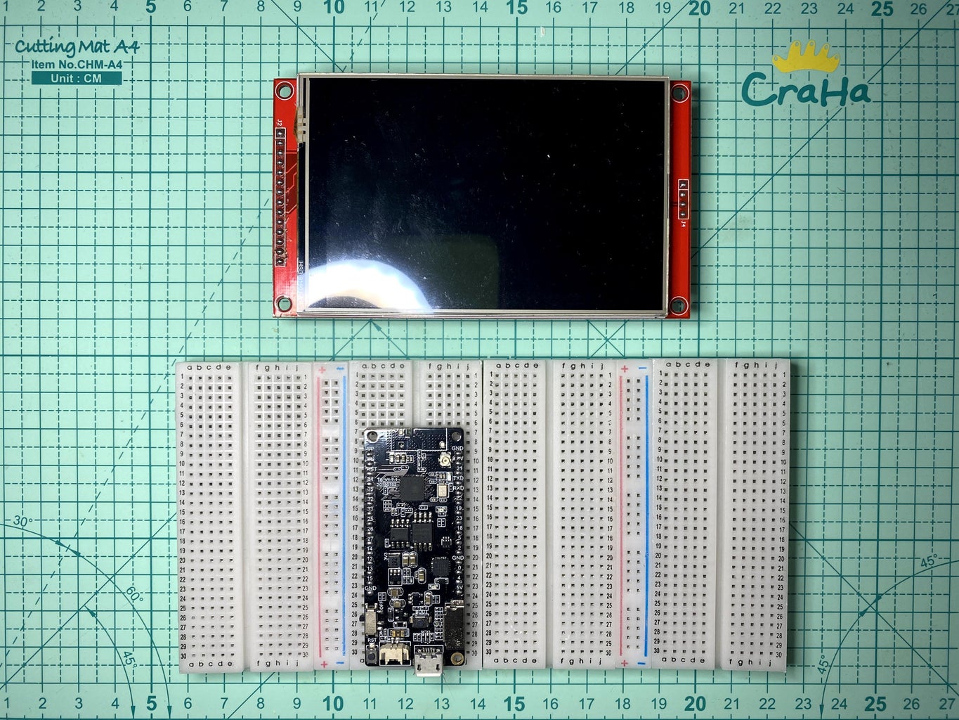
4.0 inches ST7796S SPI LCD module: https://www.aliexpress.com/af/4.0-inches-ST7796S-S...
FOUR NUMBER OF 400 holes breadboard: https://www.aliexpress.com/af/400-holes-breadboard...
TTGO T8 v1.7 ESP32 Dev Board: https://www.aliexpress.com/af/TTGO-T8-v1.7-ESP32.h...
MAX98357 I2S Amplifier module: https://www.aliexpress.com/af/MAX98357-I2S-Amplifi...
PCB Mount Mini Speaker: https://www.aliexpress.com/af/PCB-Mount-Mini-Speak...
PSP Analog joystick module: https://www.aliexpress.com/af/PSP-Analog-joystick-...
SIX NUMBER OF button key module: https://www.aliexpress.com/af/button-module.html?S...
Step 1: What Is Nofrendo?
Nofrendo is a good NES emulator that can run at full speed on a slow Pentium system. It has decent sound support, and good compatibility.
Nofrendo is developed by Matthew Conte at previous century. It can run at Windows, Unix and BeOS. Since the implementation is generalized to support different platform, many developers start develop other platforms NES emulator base on it.
Ref.:
https://www.zophar.net/nes/nofrendo.html
Step 2: Arduino-nofrendo
Github user rickyzhang82 pushed Nofrendo original source code to Github at 2018. I have forked the repository and transformed it to an Arduino library compatible layout. Simply implement all functions declared in osd.h to make it works.
Theoretically, this library can use in any Arduino platform if it have enough RAM and processing power. Since Espressif already proofed ESP32 can run Nofrendo, I base on their sample code developed an esp32-nofrendo example under examples folder.
Ref.:
Step 3: Display Options
In order to support as much display variations as possible, I changed the display implementation to use Arduino_GFX. Even large 4 inches 320x480 display like ST7796 also supported now!
Here are the Arduino_GFX supported displays variations that can fit for Nofrendo resolution:
- HX8347C 240 x 320
- HX8347D 240 x 320
- HX8352C 240 x 400 (16:9)
- HX8357B 320 x 480 (9-bit SPI and scale up make it a little bit slow)
- ILI9341 240 x 320
- ILI9481 320 x 480 18-bit color (max 20 MHz and 18-bit color make it a little bit slow)
- ILI9486 320 x 480 18-bit color
- ILI9488 320 x480 18-bit color
- M5Stack 240 x 320
- R61529 320 x 480
- ST7789 240 x 320
- ST7789 240 x 240 (square size)
- ST7796 320 x 480
Note:
- 320 x 480 display requires crop original 256 x 240 resolution to 240 x 214 and then scale up to 480 x 320.
- Width is scaled double and height is scaled 1.5 times, every 2 original lines draw 3 lines. The third line can be repeat the second line or simply leave third line remain in background color. Details implementation can be found in display.cpp.
Step 4: Audio Options
Currently arduino-nofrendo support (actually arduino-esp32 support) 2 audio output methods:
- internal DAC - ESP32 has two 8-bit DAC (digital to analog converter) channels, connected to GPIO25 (Channel 1) and GPIO26 (Channel 2), since the output is very weak it still require an extra audio amplifier for speaker output.
- external I2S DAC module - simply connect 3 signal lines and power to I2S amplifier module, it can do the jobs of DAC and audio amplifier in the same module.
Note:
The internal DAC only have 8-bit resolution and have too much silent noise, use and external I2S amplifier module can have much better result.
Step 5: Controller Options
Currently arduino-nofrendo support 3 types of controller:
- GPIO input - simply map each controller button to a GPIO, the arrow keys also have an options map to a 2-axis analog joystick
- I2C M5Stack CardKB https://m5stack.com/products/cardkb-mini-keyboard
- I2C BBQ10 Keyboard https://github.com/arturo182/BBQ10KBD
Tobe support:
- More I2C device e.g. I2C Gamepad
- Bluetooth device e.g. BT Gamepad and BT Keyboard
Note:
The default arduino-esp32 I2C interface connected to GPIO 21 (SDA) and 22 (SCL).
Step 6: File System Options
There are 3 types of nofrendo files stored in the file system:
- ROM files (*.nes) - the game
- Game save files (*.sav) - when you save in the game, the data backed up to this file
- State files (*.ss[0-9]) - when you use Nofrendo save state function, the data stored in these files
Currently arduino-nofrendo support (actually arduino-esp32 support) 3 types of file system:
- SPIFFS - normally it is the last partition of ESP32 flash
- SD - Arduino standard SPI mode SD card interface
- SD_MMC - native 1-bit or 4-bit SD mode SD card interface
Note:
SPIFFS is most easy way for initial testing. But it is hard to backup the save and state files in SPIFFS, SD or SD_MMC are recommended for long term use. Also as mentioned at the above video demo, you can treat a SD card as a game cartridge, simply swap SD cards to change the game.
Step 7: Software Preparation
Arduino IDE
Download and install Arduino IDE if you are not yet do it:
https://www.arduino.cc/en/main/software
ESP32 Support
Follow the Installation Instructions to add ESP32 support if you are not yet do it:
https://github.com/espressif/arduino-esp32
Note: Please use arduino-esp32 version 1.0.6 for this project, newer version may not compile success
Arduino ESP32 filesystem uploader
Follow the installation steps to install Arduino ESP32 filesystem uploader if you are not yet do it:
https://github.com/me-no-dev/arduino-esp32fs-plugi...
Arduino_GFX Library
Download latest Arduino_GFX libraries: (press "Clone or Download" -> "Download ZIP")
https://github.com/moononournation/Arduino_GFX
Import libraries in Arduino IDE. (Arduino IDE "Sketch" Menu -> "Include Library" -> "Add .ZIP Library" -> select downloaded ZIP file)
Arduino Nofrendo Library
Download latest Arduino Nofrendo libraries: (press "Clone or Download" -> "Download ZIP")
https://github.com/moononournation/arduino-nofrend...
Import libraries in Arduino IDE. (Arduino IDE "Sketch" Menu -> "Include Library" -> "Add .ZIP Library" -> select downloaded ZIP file)
Step 8: Breadboard Prototype

Before building your own final version of portable Arduino NES console, let's start a PoC with a breadboard prototype.
Step 9: Breadboard Patch


4 inches LCD is a big one, combine four 400 holes breadboard is large enough to handle it. However, 8 power bus strips are over-killed, cut out 6 of them and only keep 2 is good enough.
Step 10: TTGO T8 V1.7 Patch

Combine four 400 holes breadboard can fit the 4 inches LCD, but it still does not have enough room remained to place an ESP32 dev board. so it is required hide part of the ESP32 dev board under the LCD. Also hide the clumesy wiring under the LCD can make it more tidy. But I found the TTGO T8 V1.7 3D antenna cannot fit under the LCD. Since the NES console does not require Internet access, I simply tear it off :P
Note:
- it can still redirect WiFi signal to a external antenna via IPEX connector in the future.
- Bluetooth device connection also require antenna.
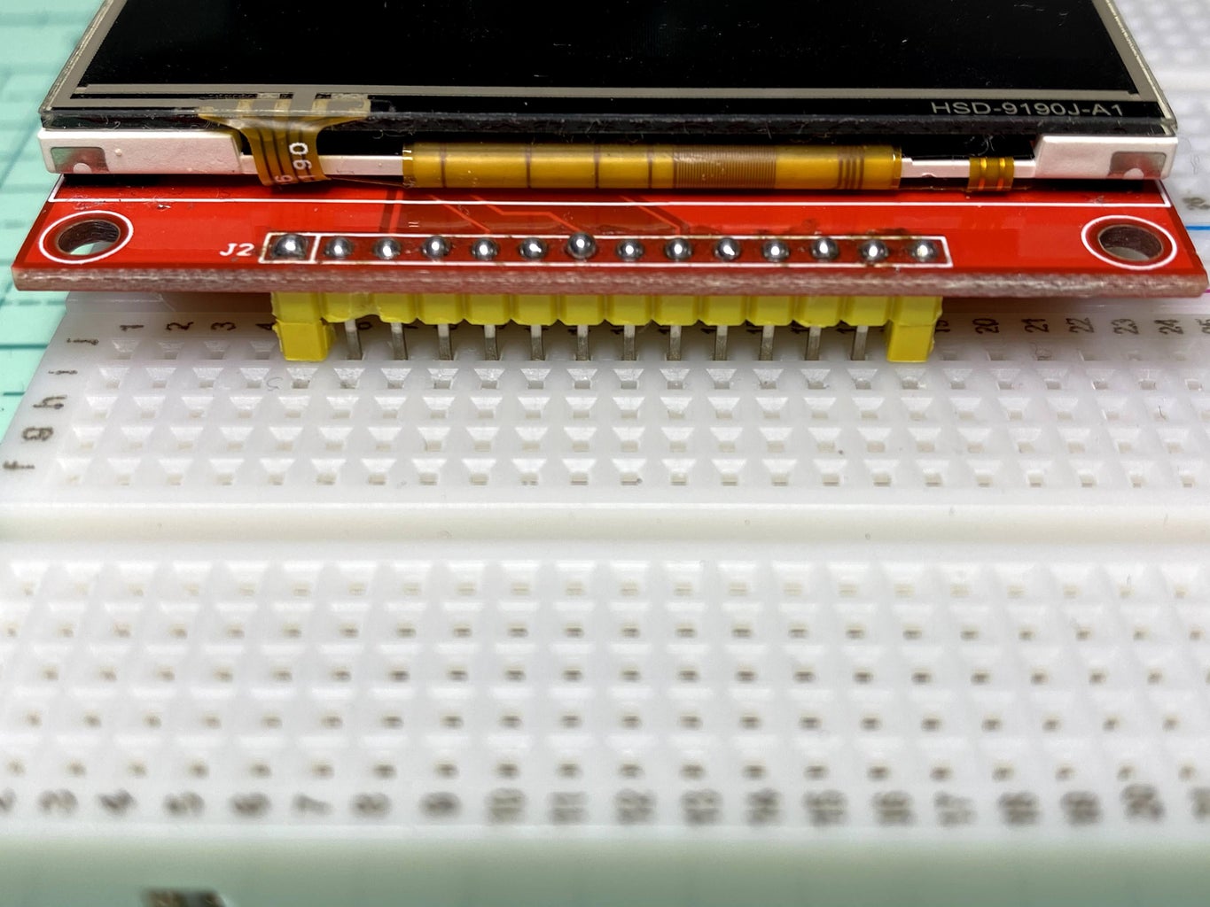
Step 11: LCD Patch

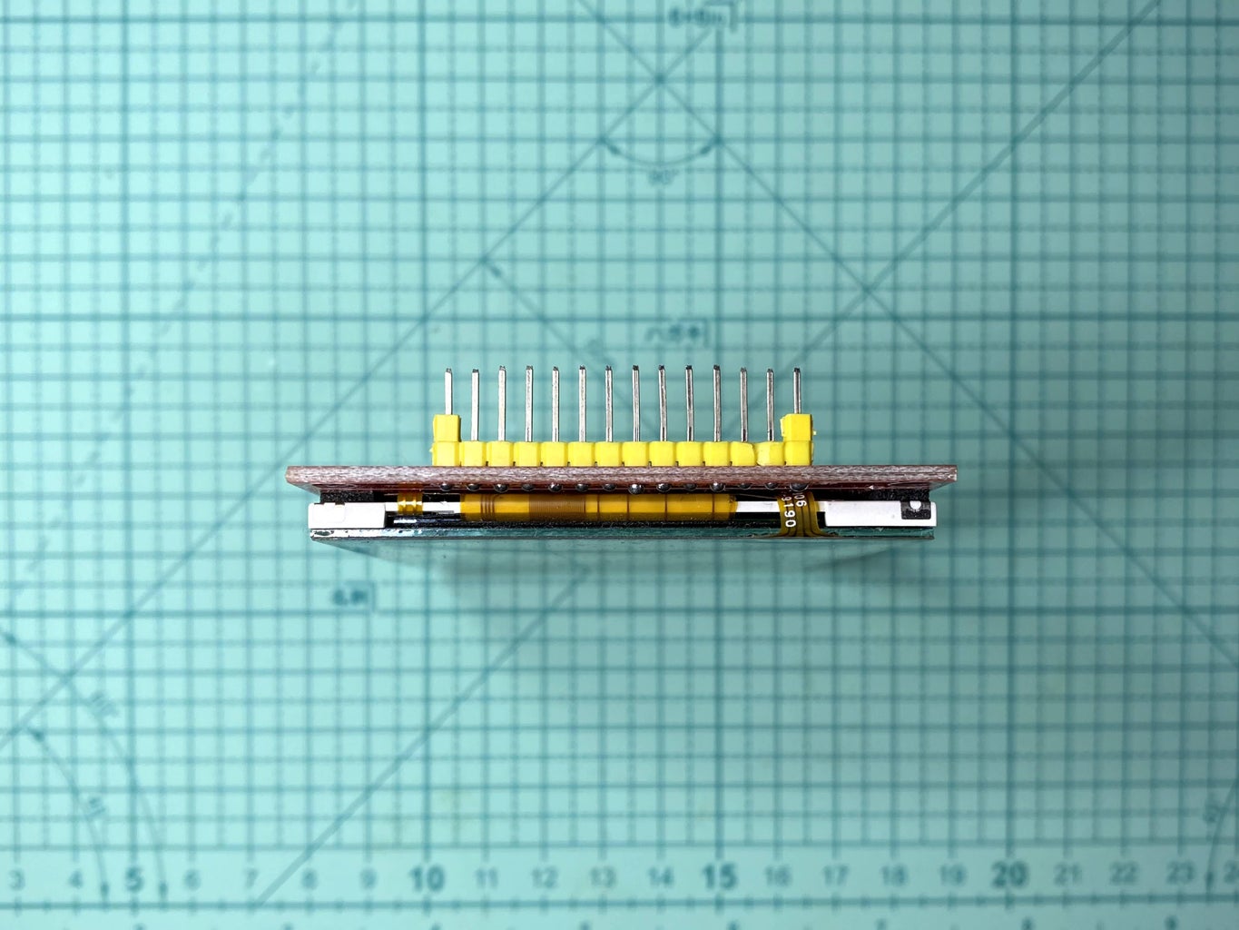

- Soldering SD pin header if not yet
- Optional: Re-soldering all LCD pins to shift the pins a little bit longer to the breadboard
- Insert a extra plastic separator to reserve more room between the breadboard and LCD
Step 12: Fix Analog Joystick


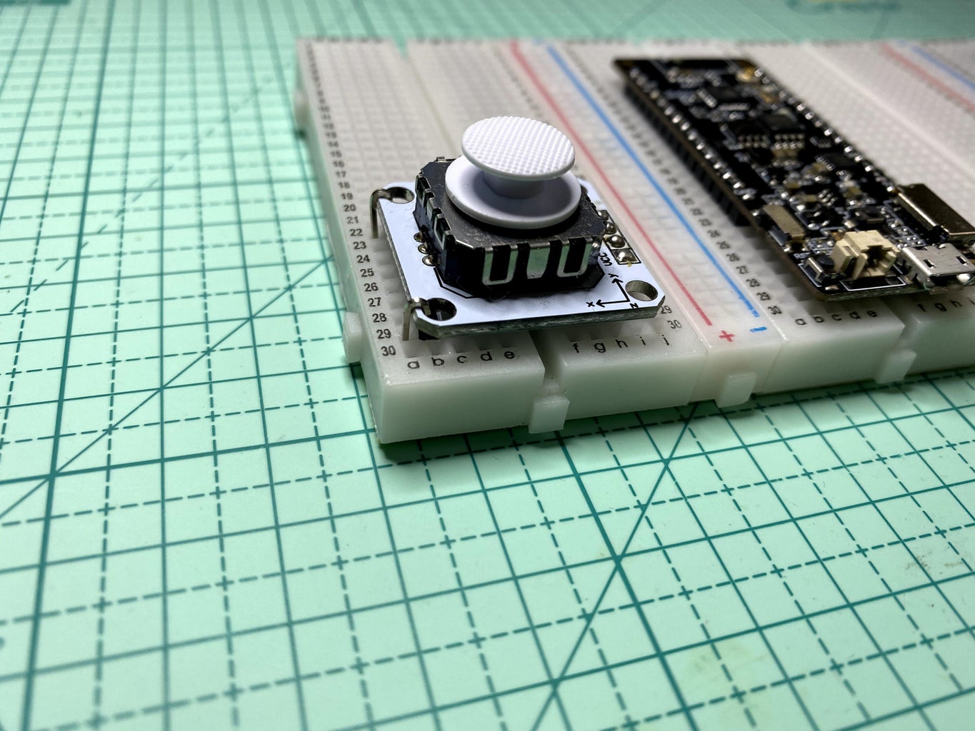
The side of analog joystick with breakout pins can fix on the breadboard very good, but the other side require some extra pins to fix it on the breadboard.
Step 13: I2S Amplifier Module Patch


The I2S Amplifier module speaker connectors are not 2.54 mm pitch (the pitch size of breadboard holes), it is required bend the pin header a little bit for soldering.
Step 14: Layout Design

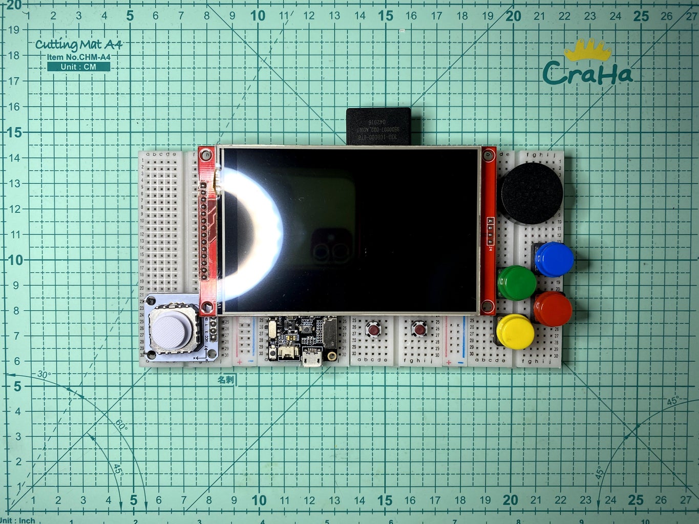
Before actual breadboard wiring, first design all components layout. And double check all components positions not conflict with the LCD.
Step 15: Pin Mapping Design

This step is optional, just make the wire neatly. Since all wires hidden behind the LCD, it is not essential.
Most ESP32 interface can remap to any GPIO pins, except SD_MMC. Since TTGO T8 v1.7 already built-in SD card slot connected to SD_MMC interface, I would like to reuse that pins to LCD SD card slot.
I have used some breadboard wires under the dev broad to redirect some GPIOs to other breadboard strips for more tidy layout:
- Analog joystick pins GPIO 34 & 35 to left bottom
- SD_MMC pins GPIO 13, 15, 2 & 14 to right top
- Start & Select button pins GPIO 26 & 27 to right bottom
- 3v3 to 2 power strips
- GND to power strips
Note:
SPI display connect 7 GPIO pins normally, it is CS, RESET, D/C, SCK, MOSI, MISO and LED. In order to reduce the number of GPIO usage to 3, some arrangement made:
- CS pull down to GND, means always enable
- Reset connect to ESP32 Reset, LCD reset while ESP32 reset
- MISO leave not connected, no need to read data from LCD
- LED connect to VCC, LCD backlight alway 100% on
Step 16: Breadboard Wiring


Here are the connection summary:
ESP32
VCC      ->  LCD VCC & LED, I2S Amplifier Module VCC, Joystick VCC
GND      ->  LCD GND & CS, I2S Amplifier Module GND, Joystick GND, all Button GND
RST      ->  LCD RST
GPIO 34  ->  Joystick Up Down Analog
GPIO 35  ->  Joystick Left Right Analog
GPIO 32  ->  LCD D/C
GPIO 33  ->  LCD MOSI
GPIO 25  ->  LCD SCK
GPIO 26  ->  Button Start
GPIO 27  ->  Button Select
GPIO 23  ->  Button X
GPIO 18  ->  Button Y
GPIO  5  ->  Button A
GPIO  4  ->  Button B
GPIO 14  ->  SD SCK
GPIO 13  ->  SD CS
GPIO 15  ->  SD MOSI
GPIO  2  ->  SD MISO
GPIO 22  ->  I2S Amplifier Module BCLK
GPIO 21  ->  I2S Amplifier Module WCLK (or called LRC)
GPIO 19  ->  I2S Amplifier Module DOUT (or called DIN)
             I2S Amplifier Module GAIN -> 100 ohm resistor -> GND (optional 15 dB gain)
             I2S Amplifier Module +ve -> Speaker +ve
             I2S Amplifier Module -ve -> Speaker -ve
Step 17: Optional Battery

TTGO T8 v1.7 dev board built-in Lipo charge and regulate circuits. Connect a Lipo Battery can make the console portable but it is not essential for prototyping.
Behind the breadboard is a big flat surface that can place a very large Lipo Battery.
Step 18: Program

- Connect the device with USB cable
- Open Arduino IDE
- Open esp32-nofrendo sample code ("File" -> "Example" -> "arduino-nofrendo" -> "esp32-nofrendo")
- Check the configuration parameters in hw_config.h and display.cpp, the default parameters is already set for this breadboard prototype
- Press Arduino IDE "Upload" button
Note:
Sometimes you need remove the SD to make the upload success.
Step 19: ROM
If you does not have any NES rom files in hand, there are many homebrewn NES rom on the web, e.g.:
http://www.nesworld.com/article.php?system=nes&dat...
I have selected a simple game called "Chase" in the "BEST HOMEBREWN NINTENDO ENTERTAINMENT SYSTEM GAMES" for the esp32-nofrendo example.
Note:
A homebrewn shooting game called "BLADE BUSTER" also recommended, but the rom size cannot fit for the dev board that does not have PSRAM. (nofrendo require load the rom file to the memory)
Step 20: Upload ROM File

The default hw_config.h parameter is set to use SD filesystem, simply copy your ROM file (*.nes) to a SD card and plug it in to make it work.
If you changed to use SPIFFS filesystem, the esp32-nofrendo example already included a "Chase.nes" ROM file in data folder.
Simply select "Tools" menu in Arduino IDE -> "ESP32 Sketch Data Upload" will upload the ROM file to ESP32 SPIFFS.
You can also copy your ROM files to data file and upload.
Note:
At this moment, esp32-nofrendo example will found the first "*.nes" file and load it.
Step 21: Status Save & Load
Status Save & Load, also called infinity recovery, is a simple cheating technique that can help you play game easier.
NES does not have button X & Y, I have used it as a status save & load buttons.
Note:
Nofrendo designed 10 slot for status save & load, currently arduino-nofrendo only can use first slot (slot 0).
Step 22: Pre-built ESP32 Console
The are few ESP32 dev device pre-built as a game console, e.g.:
- TTGO T-Watch + Game module
- ODROID-GO
- M5Stack + M5Stack CardKB
Step 23: TTGO T-Watch + Game Module

- Open esp32-nofrendo sample code ("File" -> "Example" -> "arduino-nofrendo" -> "esp32-nofrendo")
- Select "TTGO T-Watch" ("Tools" -> "Board" -> "TTGO T-Watch")
- Press Upload button
- Upload Data ("Tools" -> "ESP32 Sketch Data Upload")
Ref.:
Step 24: ODROID-GO

- Open esp32-nofrendo sample code ("File" -> "Example" -> "arduino-nofrendo" -> "esp32-nofrendo")
- Select "ODROID ESP32" ("Tools" -> "Board" -> "ODROID ESP32")
- Press Upload button
Ref.:
https://www.hardkernel.com/shop/odroid-go/
Step 25: M5Stack + M5Stack CardKB

- Open esp32-nofrendo sample code ("File" -> "Example" -> "arduino-nofrendo" -> "esp32-nofrendo")
- Select "M5Stack-Core-ESP32" ("Tools" -> "Board" -> "M5Stack-Core-ESP32")
- Press Upload button
Note:
CardKB cannot report more than 1 key pressed at the same time, so it is suitable for playing certain games.
Ref.:
Step 26: Enjoy!

It's time to build your own Arduino NES console!
Arduino IDE is a very easy to use platform. The esp32-nofrendo example only a starting point, you can add much more features on it, e.g.:
- Touch screen UI
- Game selection UI with art image like RetroPie
- Snapshot while playing
- Status slot selection
- Status save with snapshot
- Status browse and load UI with snapshot preview
- Volume setting
- LCD backlight setting

Second Prize in the
1000th Contest


