

Introduction: Arduino TFT Graphics Shield


This instructable explains how to make a 240 x 320 pixel (QVGA ) color graphics shield for your Arduino UNO R3.
The shield, which features an SPI bus and an ILI9341 display controller, plugs directly into your Arduino.
Only 5 Arduino data pins are used which leaves the other pins free for your projects.
The TFT display is the same length as your Arduino which makes for a tidy package.
The shield:
- eliminates the need for cables.
- provides a stable mount for the display
- contains the necessary 5 volt to 3 volt voltage dividers
- can be stacked on top of other Arduino shields
The estimated cost of parts is less than $20
Images
Photo 1 shows the Arduino shield powered up.
The video shows the TFT shield in action.
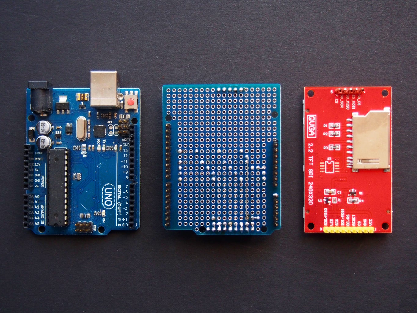
Step 1: Parts List
The following parts were obtained from https://www.aliexpress.com/:
- 1 only 2.2 Inch TFT SPI LCD Display Module 240*320 ILI9341 with SD Card Slot for Arduino Raspberry Pi 51/AVR/STM32/ARM/PIC [1]
- 1 only Prototype PCB Expansion Board For Arduino ATMEGA328P UNO R3 Shield FR-4 Fiber PCB Breadboard 2mm 2.54mm Pitch
The following parts were obtained locally:
- 5 only 2K2 ohm 1/8 watt metal film resistors
- 5 only 3k3 ohm 1/8 watt metal film resistors
- 1 only 40 pin header terminal strip 0.1"/2.54mm pitch for PCBs
- 10 amp tinned copper fuse wire
The estimated cost of parts is less than $20
Step 2: Wiring Diagram
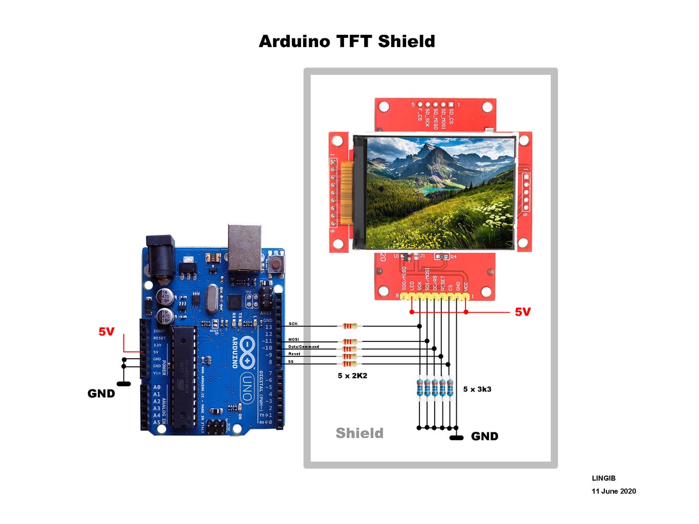


The TFT module accepts 5 volts, as it has a 3 volt voltage regulator, but each of the TFT inputs expects 3 volts.
The 2K2 | 3K3 voltage dividers reduce the Arduino 5 volt outputs down to 3 volts.
Images
- Photo 1 shows the TFT wiring diagram.
- Photo 2 shows the matching shield
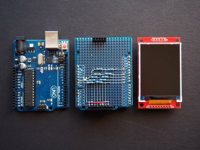
- Photo 3 shows the shield underside
- Photo 4 shows is a top view of the shield
- Photo 5 shows the assembled unit
Testing
- Unplug the TFT display from the shield
- Insert the shield into your Arduino
- Plug your Arduino into your computer
- Check that each voltage divider junction measures 3 volts.
- Disconnect the Arduino from your computer
- Plug in the TFT display
- You are now ready to go.
Step 3: Software
Three library files are required in addition to the attached code
Step 1
Download the following library files:
- https://github.com/adafruit/Adafruit_ILI9341
- https://github.com/adafruit/Adafruit-GFX-Library
- https://github.com/adafruit/Adafruit_BusIO
Each of the above files are in zip format and will appear in your download folder
Step 2
Select and install each of the above libraries using your Arduino IDE :
- Click “Sketch | Include Library | Add Zip Library ... |Adafruit_ILI9341-master.zip”
- Click “Sketch | Include Library | Add Zip Library ... |Adafruit-GFX-Library-master.zip”
- Click “Sketch | Include Library | Add Zip Library ... |Adafruit_BusIO-master.zip”
Step 3
From your Arduino IDE:
- Copy the attached “graphicstest2.ino” file to an Arduino sketch [1]
- Save the sketch as “graphicstest2” then upload it to your Arduino
Note
[1]
The contents of “graphicstest2.ino” is identical to the library example file ”... |Arduino | libraries | Adafruit_ILI9341-master | examples | graphicstest | graphicstest.ino” except that some additional display module pins have been defined in the header.
The code for the Cover photo is also included.
Attachments

Step 4: Summary
The instructable describes how to make a TFT graphics shield for your Arduino Uno R3
The display size is 320 x 240 pixels (QVGA)
The SPI shield plugs directly into your Arduino
Only 5 Arduino data pins are required
The TFT display is the same length as your Arduino which makes for a tidy package.
The estimated cost of parts is $20
Click here to view my other instructables.

Participated in the
Arduino Contest 2020

![Tim's Mechanical Spider Leg [LU9685-20CU]](https://content.instructables.com/FFB/5R4I/LVKZ6G6R/FFB5R4ILVKZ6G6R.png?auto=webp&crop=1.2%3A1&frame=1&width=306)


