

Introduction: Arduino Thin Client


This instructables show how to build an Thin Client with a WiFi capable Arduino dev board, e.g. ESP32 or Raspberry Pi Pico W.
Supplies
Any network capable Arduino dev device, with touchscreen display is preferred.
Step 1: What Is Thin Client?
Thin Client is an minimalistic hardware that provide a user interface connect the user to the actual processing machine. E.g. using a low cost laptop remote (VNC/RDP) to a Windows server, the laptop is a Thin Client.
Thin Client not require a high processing power device since all jobs are running on the server, so it is called Thin Client.
Thin Client is not a new thing, in last century, the relation of terminal and mainframe is a good example. Terminal is a Thin Client.
Thin Client has many advantage if it can be made from low cost hardware. But how low it can be?
Sun Microsystems Sun Ray is a good example of GUI Thin Client in last century, it even has tailor-made low cost low power CPU but the unit cost still very high.
Then Intel introduce a low cost CPU, ATOM, many vendors (e.g. HP, Dell, etc) use ATOM provide Thin Client solution. However, it still need connect to a monitor, keyboard and mouse. After counted the cost of these components, the total cost is not much lower than a standard desktop computer.
How about using an WiFi capable Arduino dev board with touchscreen to build a Thin Client? This low cost should be much reasonable to call it as a Thin Client.
Ref.:
https://www.oreilly.com/library/view/learning-dcom/9781449307011/ch01s01.html
https://en.wikipedia.org/wiki/Thin_client
https://www.forcepoint.com/cyber-edu/thin-client
https://www.fortinet.com/resources/cyberglossary/thin-client
https://www.techtarget.com/searchnetworking/definition/thin-client
Note:
If you search Thin Client on the web, you can see many big vendors providing Thin Client solutions recently.
Step 2: Communication Protocol
Many parties tried implement their own Thin Client, so many communication protocol appeared. Sun Ray has it own SRSS communication protocol to access the server, then it support RDP afterward. RDP is a common protocol for remote Microsoft Windows machine but RDP server not easy implement in other OS.
VNC is a common name of various remote softwares, it use RFB protocol communicate between client and server. Since it is open source, the server side can be implemented in various OS such as Linux, MacOS and Windows. The client side also implemented in various desktop environment, mobile device, it even have Java version client and can run on a web browser.
Since the RFB protocol is open source, it can extend to any platforms. Links2004 has implemented the VNC client in Arduino platform and this is the starting point of this project.
Ref.:
Step 3: The Bottleneck
Links2004's VNC client is fine for a normal Arduino ILI9341 display. But ILI9341 only have resolution of 320x240, it is much lower than a normal desktop monitor. Most recent OS windows manager assume you have a much bigger resolution.
Some larger display can have 800x480, I think it is good enough for simple remote GUI operation. But larger display introduce few bottleneck:
- ESP32 SPI data frequency can reach 80 MHz than means full frame refresh rate is around 80 MHz / (800 * 480 * 16 bit color) ~= 13 fps.
- In my rough measure, the data rate of both ESP32 and Pico W only can reach a little bit higher than 1 MBps. If using the VNC Hextile encoding, it only reach 6-7 fps if a portion of screen have continuous update.
So we need a faster display interface and a better VNC encoding to overcome the bottlenecks.
Step 4: Faster Display Interface
Actually, 800x480 display seldom have SPI only interface. It can drive with 8-bit/16-bit parallel interface(or called MCU), RGB interface or MIPI serial mode.
8-bit parallel interface included too much bitwise operations overhead while actual use and only have half bandwidth of 16-bit parallel interface, so I prefer 16-bit than 8-bit.
RGB interface display is lower cost for a bigger screen, but as I know only ESP32-S3 support this interface and it consume a portion of CPU time constantly even no any screen update.
MIPI serial mode is not opened source and it need paid for using it, so it is not for hobbyist scope.
Ref.:
Step 5: Implement ZRLE
Virtual Network Computing (VNC) is a graphical desktop-sharing system that uses the Remote Frame Buffer protocol (RFB) to remotely control another computer.
RFB is very flexible, the client and server can determine the communication encoding by negotiation. Links2004 implemented Raw, RRE, CoRRE and Hextile in VNC client. Most of time server select using Hextile encoding because no better encoding available. IN RFC6143 there are still a ZRLE encoding not yet implemented. The Z prefix means the data is zlib compressed. That means it is require decompress the zlib data before decoding, so it need more memory resource and more processing power. But as we mentioned in previous steps, one of the bottleneck is data bandwidth, the data compression can help to overcome this limit.
In rough measure, ZRLE encoding can help improve the continuous partial screen update frame rate from 6-7 fps to 15-20 fps. You may find more testing video in my Twitter.
The VNC client with ZRLE encoding support version can be found here:
https://github.com/moononournation/arduinoVNC.git
Note:
There are much other encoding after RFC6143, but it is not open documented and not all VNC server can support those encoding.
Ref.:
https://en.wikipedia.org/wiki/RFB_protocol
Step 6: Prepare VNC Server
There are various VNC server solution available for various OS. I cannot mention it all here, but most free solution can simply download and install to get it works.
If you do not have a VNC server host yet, you may make a quick one with docker:
docker run -p 5901:5901 -e VNC_COL_DEPTH=16 -e VNC_PW=PleaseInputYourPasswordHere --shm-size=256m accetto/ubuntu-vnc-xfce-firefox-g3
The demo video in this project all connecting to this VNC server docker image instant.
Ref.:
Step 7: Software Preparation
Arduino IDE
Download and install Arduino IDE latest 1.x version if not yet:
https://www.arduino.cc/en/software
Arduino-ESP32 (Optional)
Follow installation step to add Arduino-ESP32 support if not yet:
https://docs.espressif.com/projects/arduino-esp32/en/latest/installing.html
Arduino-Pico (Optional)
Follow installation step to add Arduino-Pico support if not yet:
https://github.com/earlephilhower/arduino-pico
Arduino_GFX Library
Open Arduino IDE Library Manager by select "Tools" menu -> "Manager Libraries...". Search "GFX for various displays" and press "install" button.
You may refer my previous instructables for more information about Arduino_GFX.
ArduinoVNC Library
This project use a enhanced version ArduinoVNC Library, you need import this library manually.
Download and import the ArduinoVNC library to Arduino IDE:
https://github.com/moononournation/arduinoVNC.git
You may refer to Arduino Documentation for the details on how to import library to Arduino IDE
Step 8: Configuration

Select "File" menu in Arduino IDE -> "Examples" -> "GFX Library for Arduino" -> "ArduinoVNC"
Fill your WiFi setting:
const char *SSID_NAME = "YourAP";
const char *SSID_PASSWORD = "PleaseInputYourPasswordHere";
Fill your VNC server setting:
const char *VNC_IP = "192.168.12.34";
const uint16_t VNC_PORT = 5901;
const char *VNC_PASSWORD = "PleaseInputYourPasswordHere";
Change touchscreen setting in "touch.h" and keyboard setting in "keyboard.h".
Step 9: Mouse Input
Thin Client mainly have 2 input devices, keyboard and mouse. In GUI operation, mouse input is more common than keyboard. So we need to find a mouse input device first. Arduino dev device cannot direct use a USB mouse but still have resistive/capacitive touchscreen, analog joystick or push buttons can use. As we are already familiar with operating smart phone, touchscreen should be the best option.
The above demo video ESP32-S3 dev device is:
https://www.aliexpress.com/item/1005004788147691.html
The "touch.h" show 3 types of touchscreen implementation:
- FT6X36: https://github.com/strange-v/FT6X36.git
- GT911: https://github.com/TAMCTec/gt911-arduino.git
- XPT2046: https://github.com/PaulStoffregen/XPT2046_Touchscreen.git
But it is not the limit, you can add any touchscreen support there. Just follow the current implementation and add few lines of code...
Step 10: Keyboard Input
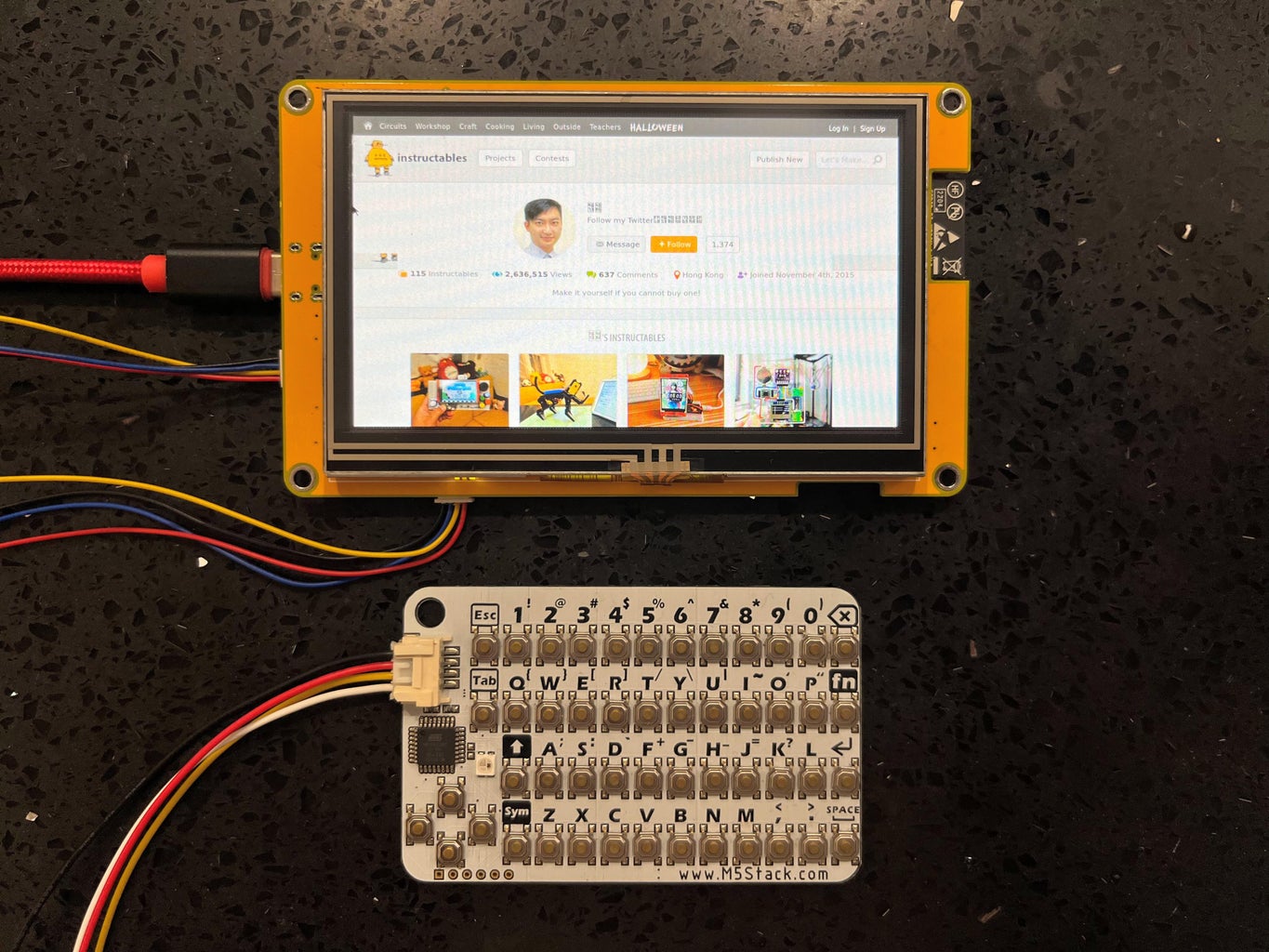
In GUI operation, Keyboard is just an optional input device. But it still handy if you need some typing. There are 2 I2C keyboards available for Arduino:
More tailor-made I2C Keyboard can be found at Tindie:
Step 11: Select Dev Device


There are various Arduino dev device with WiFi support, mainly are ESP32 family and also some ESP8266, Raspberry Pi Pico W or RTL8720. For this project, it is better select a dev device with a touchscreen, the screen size and resolution depends on your actual usage.
Connecting an I2C keyboard requires an I2C port, so the dev device is better breakout the I2C(or called Grove) port. If no I2C available, ESP32 family can use any 2 GPIOs map as I2C port. So as show on the above pictures, you just need connect 5V, GND and 2 GPIO pins to the I2C keyboard can do the job.
Note:
Besides WiFi, there are still wire connection, but not too much dev device exists. Teensy 4.1 with RJ45 is an option and ESP32 with RJ45 is another option. I may test these options later on, you may follow my Twitter to see the status.
Step 12: Raspberry Pi Pico W
It is not easy to find a Pico W dev device with a big screen. Arduino_GFX implemented a 16-bit parallel interface in Pico W(Arduino_RPiPicoPAR16), so you can find a larger screen(most probably 4 inches) with touchscreen module connect to it easily.
Step 13: RTL8720
RTL8720 support SPI and software 8-bit parallel interface, it can support large screen but don't expect the display refresh rate too much. In contract, this is the only Arduino dev board support 5GHz WiFi recently, so it have some advantages on the connectivity.
Step 14: What's Next?
- Battery powered, make it more portable
- Design a better layout I2C keyboard, more keys like a desktop keyboard
- Design a Case, make it can stand on your desktop and easy to hold in hand
- Enhance security protocol support, make it possible connect to cloud securely
Runner Up in the
Microcontroller Contest


![Tim's Mechanical Spider Leg [LU9685-20CU]](https://content.instructables.com/FFB/5R4I/LVKZ6G6R/FFB5R4ILVKZ6G6R.png?auto=webp&crop=1.2%3A1&frame=1&width=306)


