

Introduction: Arduino Watch


This Instructables show how to make a Arduino Watch from Arduino Watch Core.
Step 1: Preparation
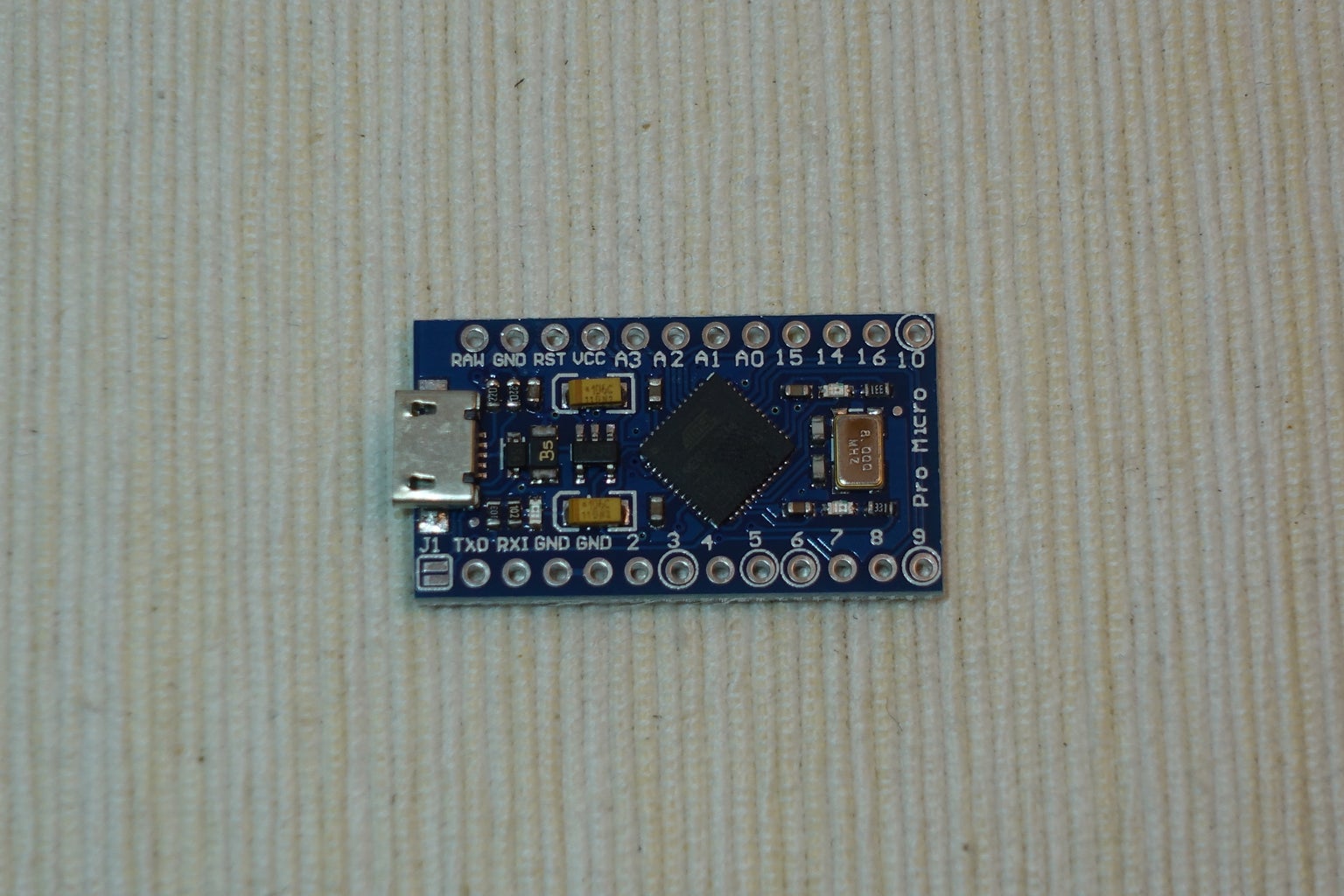


Arduino Dev Board
This time I am using Sparkfun Pro Micro 3.3 V 8 MHz dev board.
Watch Display
This time I am using a ST7789 1.3" IPS LCD.
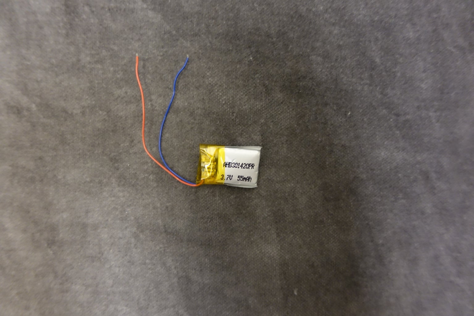
Lipo Battery
I have some 301420 Lipo battery in hand.
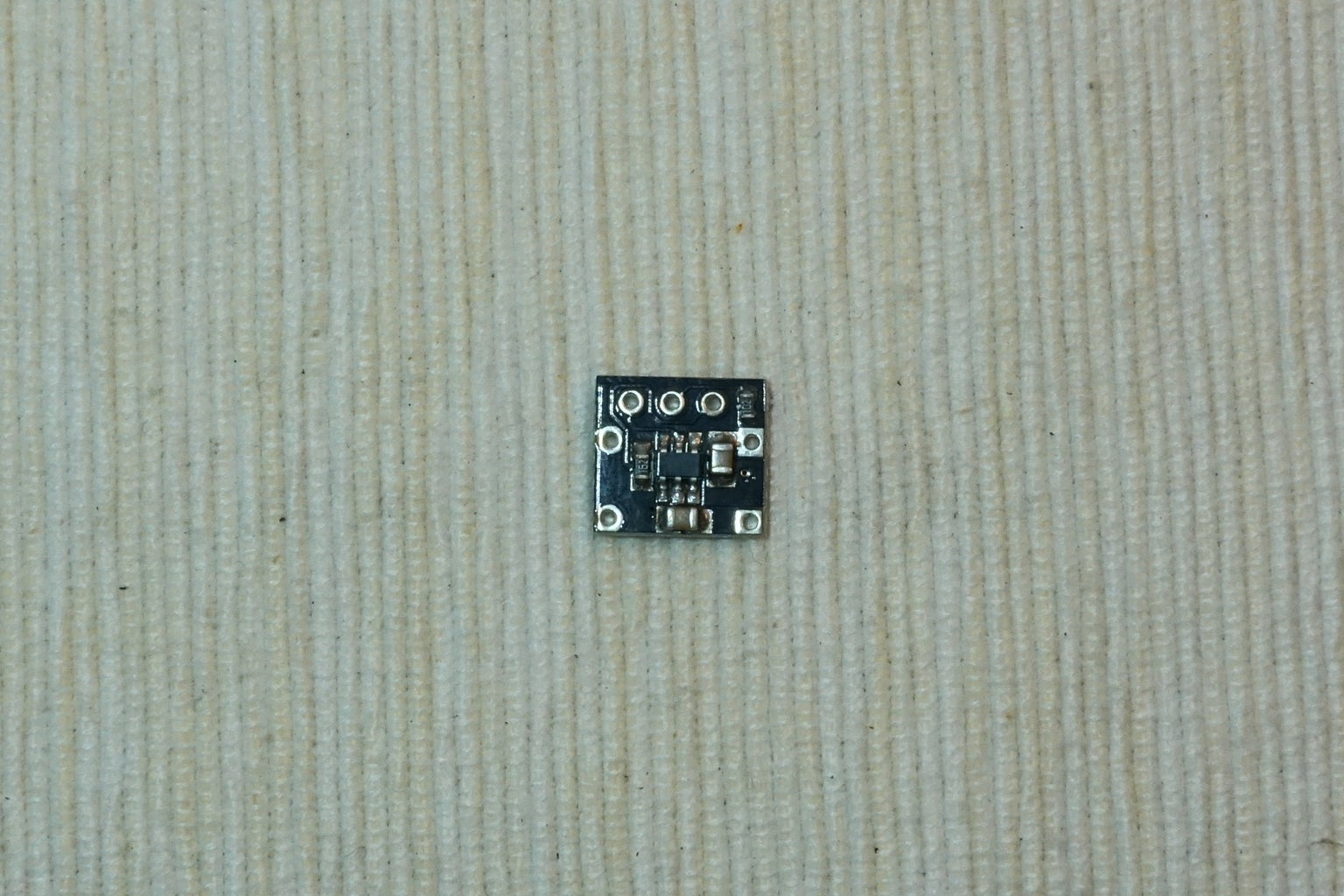
Lipo Charge Board
I have some 15 mm x 15 mm Lipo charge board in hand.
RTC Chip
This time I am using DS3231M, it built-in crystal oscillator, no extra component required
RTC Battery
This is optional, in case you want to keep the time even Lipo battery used up. MS412FE is a tiny 1 mAh rechargeable battery, according to the RTC datasheet 1 mAh already can keep time many days.
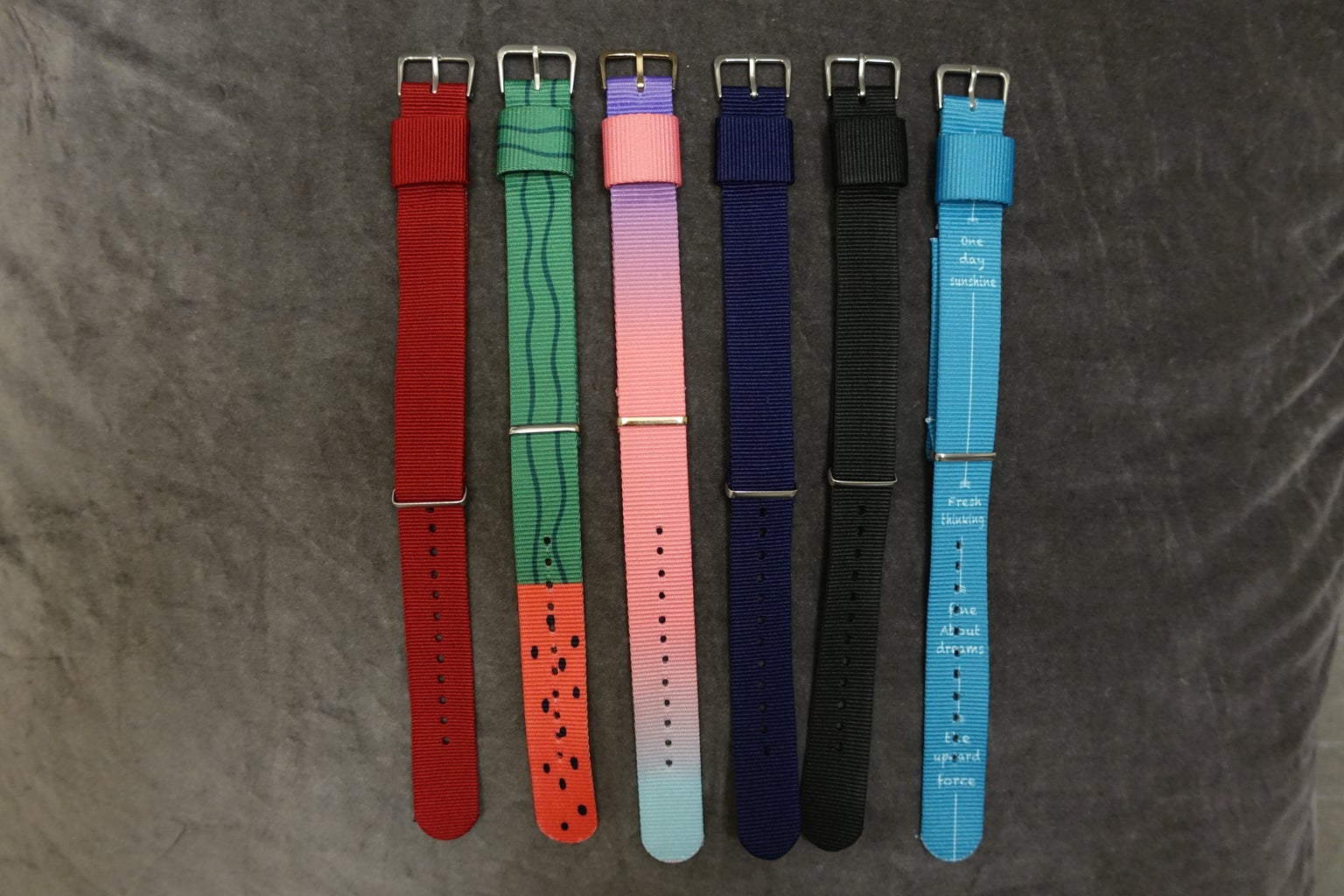
Watch Strap
I have ordered some 20 mm width fabric canvas watch strap.
Others
A diode e.g. 1N5822, four 6 mm M2 screws, copper foil tape and some wires
Step 2: Fixing Dev Board & LCD
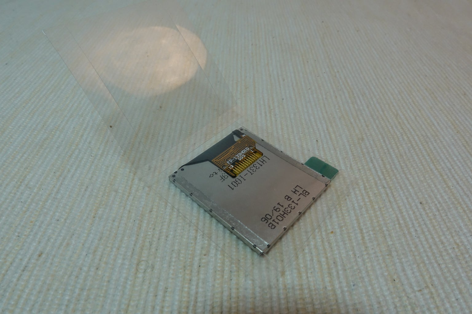

Use a small piece of PET plate to stick the Pro Micro and IPS LCD together.
Step 3: Connect GND


Read the LCD datasheet provided by your vendor.
Cut a little copper foil tape just touch all GND pins and LED negative pins and fix it on the FPC plate. Then soldering the pins with copper foil tape.
Step 4: Connect Power Pins

Connect dev board GND Pins to the copper foil tape. Connect Vcc pins to LCD Vcc pin.
Step 5: Connect LCD Pins

Here are the connection summary:
LCD  -> Arduino
LED+ -> GPIO 10
SDA  -> GPIO 16(MOSI)
SCL  -> GPIO 15(SCLK)
RST  -> GPIO 18(A0)
DC   -> GPIO 19(A1)
CS   -> GPIO 20(A2)
Step 6: Remove Power Led


The power LED always on and consume over 1 mA continuously, so it is better remove it. Unsoldering and remove the LED carefully.
Step 7: Connect Lipo Battery

Here are the connection summary:
Charge Board +ve in      -> Dev Board J1 connector near the USB socket (5V)
Charge Board -ve in      -> Dev Board GND Pin
Charge Board Battery +ve -> Lipo +ve -> 1N5822 diode -> Dev Board Raw Pin
Charge Board Battery -ve -> Lipo -ve
Note:
Most Lipo charge board is better use 5V power as input. However, Pro Micro dev board do not provide USB 5V pin. Fortunately, the J1 connector near the USB socket is actually connected to USB 5V pin. Beware not soldering 2 connectors together.
Step 8: Connect RTC


DS3231M is very tiny and it require to connect to a tiny battery, please be patient connect all together:
DS3231M pin 2 (Vcc)  -> dev board Vcc
DS3231M pin 5 (GND)  -> dev board GND, MS412FE RTC battery -ve
DS3231M pin 6 (VBAT) -> MS412FE RTC battery +ve
DS3231M pin 7 (SDA)  -> dev board GPIO 2 (SDA)
DS3231M pin 8 (SCL)  -> dev board GPIO 3 (SCL)
Step 9: Connect Motion Sensor


As mentioned in my previous instructables, I use 2 vibration sensors as a motion sensor to trigger the dev board wake up pin.
However, the watch have no room to fit 2 5 mm vibration sensors. I have tried replace with a 3 mm vibration sensor and tested few days. It is too easy mis-triggered wake up and the battery drain up within a day.
I am still testing some other methods to avoid mis-triggered wake up. you may follow my Twitter to get the latest findings.
Step 10: Program

Please follow my previous instructables to program the dev board.
Step 11: 3D Print Watch Case

Please download and print the watch case: https://www.thingiverse.com/thing:3799868
Step 12: Happy Time!

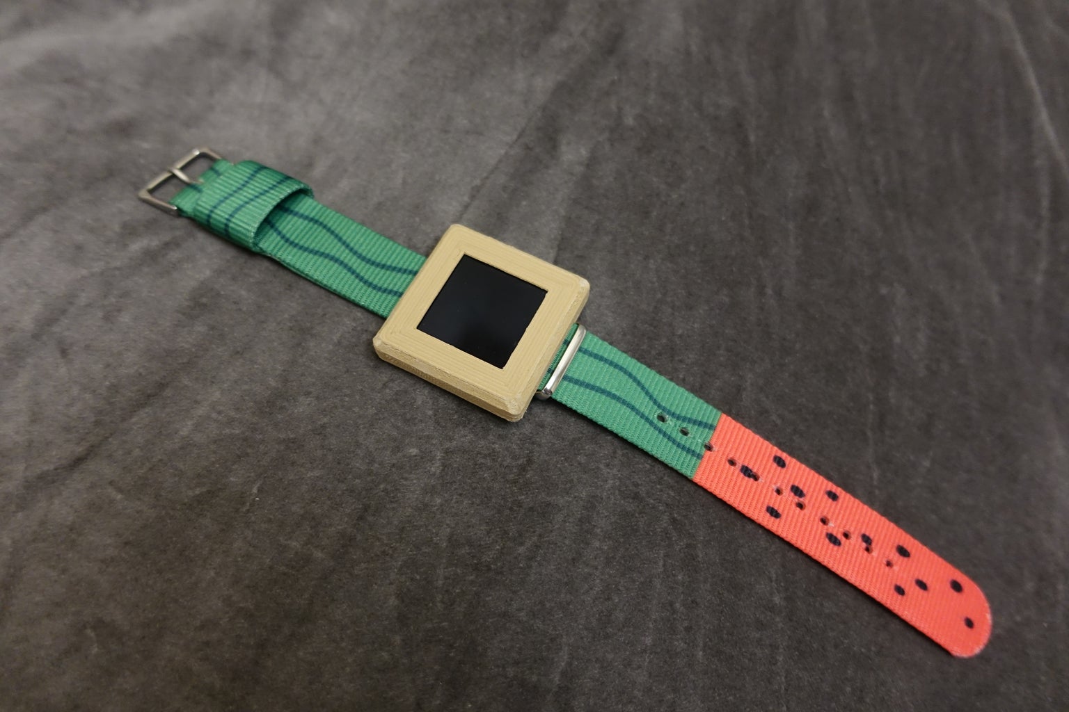

It's to show off what you have done to your friends!
And also you can:
- program and design your own watch face
- add more sensors or components to make it become a smart watch
- design your own watch case


![Tim's Mechanical Spider Leg [LU9685-20CU]](https://content.instructables.com/FFB/5R4I/LVKZ6G6R/FFB5R4ILVKZ6G6R.png?auto=webp&crop=1.2%3A1&frame=1&width=306)


