

Introduction: Arduino_GFX


This instructables introduce a color display graphic function (GFX) Library for Arduino.
The content is intended to be updated from time to time, I will add more details if Arduino_GFX added more features. You can also help me enrich the content by leaving comments below.
Step 1: What Is Arduino_GFX?

Arduino_GFX is a color display GFX library for Arduino.
"for Arduino" means aims to support as much Arduino Platform as possible. And also aims to support as much display as possible in various interfaces.
Most hobbyist electronics market color display is SPI and most Arduino Platform support SPI. Arduino_GFX utilize Arduino native SPI class as basic interface, HWSPI, so Arduino_GFX is already virtually ready for most platform and most display.
Step 2: Software Design
Arduino_GFX start rewrite from Adafruit_GFX and used many features from LovyanGFX and TFT_eSPI, but the high level design is a little bit like Ucglib. Arduino_GFX decouple display driver and data interface into 2 separate class. It gives much more flexibilities, for example, ILI9341 display can use:
- 8-bit SPI
- 9-bit SPI
- 6-bit parallel
- 8-bit parallel
- 9-bit parallel
- 16-bit parallel
- 18-bit parallel
Arduino_GFX support four of them:
- 8-bit SPI
- 9-bit SPI
- 8-bit parallel
- 16-bit parallel
Simply feed different data bus class to "Arduino_ILI9341" display class can support various type of ILI9341 display breakout module.
Ref.:
Step 3: Library Installation

- Open Library Manager in Arduino IDE: Tools menu -> Manage Libraries...
- Search "color display gfx" or "GFX Library for Arduino"
- select "GFX Library for Arduino" and Install
Or you can download the latest code from GitHub and import to library folder yourself:
https://github.com/moononournation/Arduino_GFX
Ref.:
Step 4: Ease of Use
Simple Declaration
#include <Arduino_GFX_Library.h>
Arduino_DataBus *bus = new Arduino_HWSPI(16 /* DC */, 5 /* CS */);
Arduino_GFX *gfx = new Arduino_ILI9341(bus, 17 /* RST */);
The declaration only requires 3 lines, using create_default_Arduino_DataBus() or create_default_Arduino_GFX() still can make it simpler. This 2 functions will mention in later steps.
And Simple Usage
gfx->begin();
gfx->fillScreen(BLACK);
gfx->println("Hello World!");
Step 5: Ease of Switching Hardware
Arduino_GFX write as generic as possible to support multi-platform. Switching dev board no need to change any code related to GFX function. Switching display simply replacing the GFX class, e.g. switching ILI9341 display to ST7789 IPS display will be:
// Arduino_GFX *gfx = new Arduino_ILI9341(bus, TFT_RST, 0 /* rotation */, false /* IPS */);
Arduino_GFX *gfx = new Arduino_ST7789(bus, TFT_RST, 0 /* rotation */, true /* IPS */);
Step 6: Manual Set Frequency
Every platform defined the default SPI speed, ESP family is 40 MHz, AVR family is 4 MHz, ...etc. When you initial the gfx class, "gfx->begin();", you can pass the frequency value in it to override the default value:
gfx->begin(80000000); // 80 MHz
Step 7: LED Backlight
As you can see the the declaration in previous step, there are no need to pass the LED pin to both class. This is because the LED on or off is not controlled by the display driver, in most case it is direct controlled by the MCU GPIO. Sometimes it is controlled by a dedicated power control chips; Sometimes there is no LED backlight, e.g. OLED.
So Arduino_GFX leave LED backlight control to the main program.
The most lazy way is just connect the LED pin to Vcc, but it may take a risk of burn out LED if the breakout board not have enough protection. So it is better using a GPIO:
pinMode(TFT_BL, OUTPUT);
digitalWrite(TFT_BL, HIGH);
Or if you want brightness control with PWM:
pinMode(TFT_BL, OUTPUT);
analogWrite(TFT_BL, 127); /* 0-255 */
Please note ESP32 not implemented analogWrite(), it have its own LED control function:
ledcSetup(0 /* LEDChannel */, 5000 /* freq */, 8 /* resolution */);
ledcAttachPin(TFT_BL, 0 /* LEDChannel */);
ledcWrite(0 /* LEDChannel */, 127); /* 0-255 */
Step 8: Benchmark
Arduino_GFX is not putting speed at the first priority, but still paid much effort to make the display look smooth. Let's compare the speed with a most well known GFX library and 2 fastest GFX libraries.
Arduino IDE: 1.8.15
arduino-esp32: 1.0.6
PSRAM option: disable
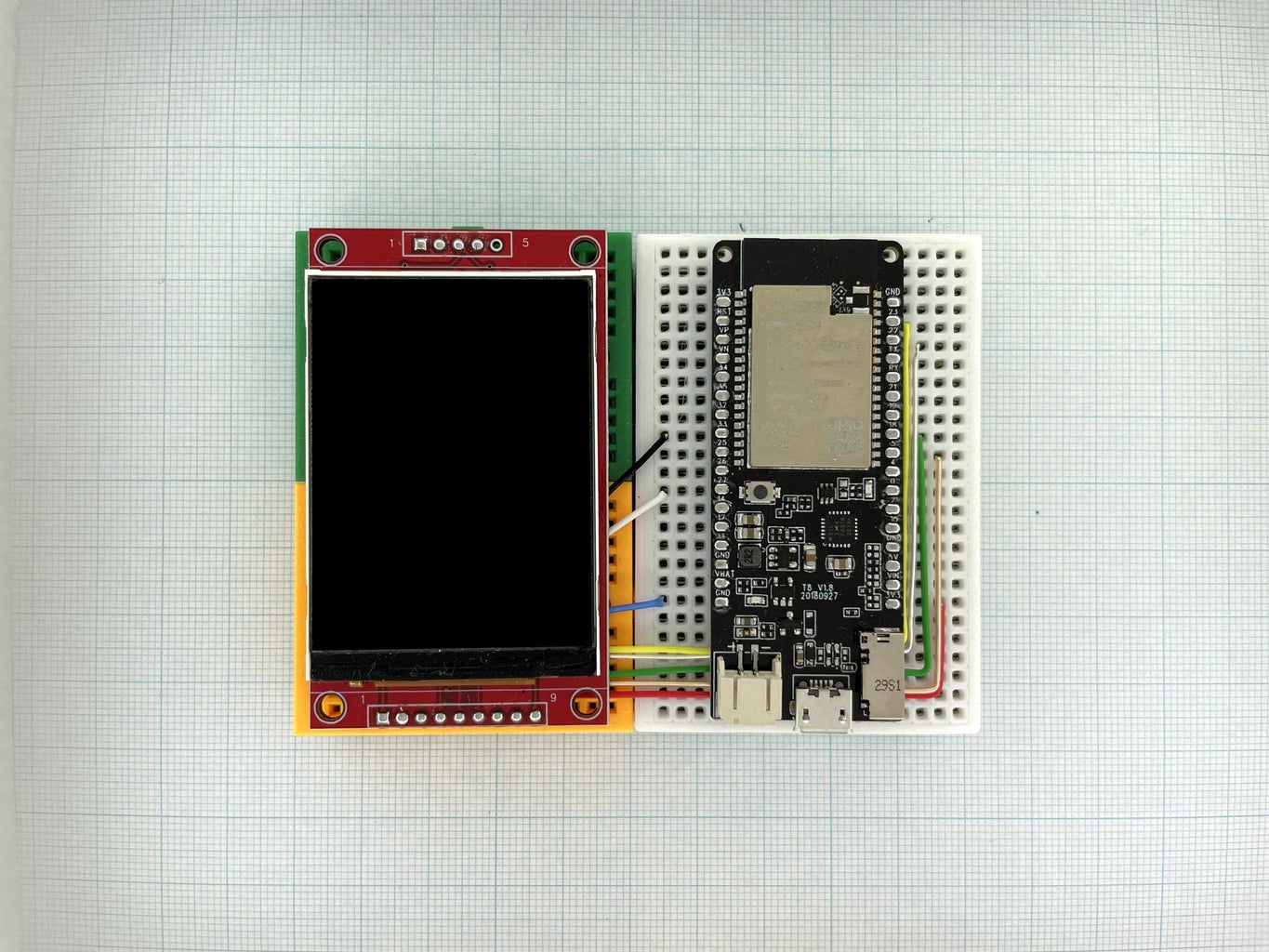
Dev Board: TTGO T8 v1.8
Color Display: ILI9341
Interface: SPI
SPI Frequency: 40 MHz
Test Code: https://github.com/moononournation/Arduino_graphicstest_PDQ.git
Test Date: 2021 Jun 16
| Benchmark | Adafruit_GFX | Arduino_GFX | Lovyan_GFX | TFT_eSPI |
| ------------------ | ------------ | ------------ | ------------ | ------------ |
| Screen fill | 195,782 | 160,094 | 154,341 | 155,938 |
| Text | 97,662 | 18,960 | 22,473 | 21,752 |
| Pixels | 1,365,211 | 903,549 | 867,702 | 775,781 |
| Lines | 1,062,311 | 412,026 | 269,060 | 264,950 |
| Horiz/Vert Lines | 17,637 | 14,197 | 13,692 | 13,833 |
| Rectangles-filled | 406,817 | 332,696 | 320,761 | 323,908 |
| Rectangles | 11,641 | 9,254 | 8,545 | 8,714 |
| Triangles-filled | 150,941 | 118,010 | 105,661 | 109,675 |
| Triangles | 58,843 | 23,570 | 15,884 | 16,277 |
| Circles-filled | 76,739 | 52,170 | 42,787 | 45,827 |
| Circles | 118,125 | 40,955 | 25,959 | 25,269 |
| Arcs-filled | N/A | 33,381 | 21,546 | N/A |
| Arcs | N/A | 66,054 | 47,901 | N/A |
| Rounded rects-fill | 408,534 | 338,136 | 318,882 | 323,189 |
| Rounded rects | 43,185 | 21,562 | 13,089 | 15,371 |
Step 9: Why Run "Fast"?
Arduino_GFX write as generic as possible to support multi-platform; And use OO parent class to standardize various data bus class and display class API. These design have a little bit overhead.
Even it makes Arduino_GFX cannot run as fast as fine tuned Lovyan_GFX or TFT_eSPI, the figures is "very near" :P
Here is some design to make Arduino_GFX run fast:
- Tailor-made data bus classes. Arduino_GFX decouple data bus operation from display driver, it is more easy to write individual data bus class for each platform. E.g. NRFXSPI data bus class can run much faster than general HWSPI data bus class in Arduino Nano 33 BLE platform.
- Stick to 16-bit color space. 24-bit color is overkilled for most MCU and also most color display support 16-bit color (except ILI948* in SPI mode). Stick to 16-bit color only can simplify the implementation, run faster and reduce library size footprint.
No read operation. Since not all display provide read back graphic memories API, Arduino_GFX skip read operations at all. It can reduce the library size footprint and sometimes reduce the operation time.
Step 10: Size Does Matter?

Yes, if you are using the MCU with limited program space, e.g. Arduino Nano only have 32 KB program space (exclude the size of boot loader, maximum is 30720 bytes).
In early development stage, once I added the Arcs function to PDQgraphicstest example, I found it cannot fit in Arduino Nano. A display library used up all program space means you cannot do any thing in the project. It is not acceptable, so I raise an issue in GitHub myself:
https://github.com/moononournation/Arduino_GFX/iss...
After various fine tuning and tradeoff, now PDQgraphicstest use 28530 bytes (92%); And HelloWorld example use 11496 bytes (37%), I thing it is good enough for many projects.
Step 11: 2 Hardware Factors
When you design your display project, there are 2 variable hardware factors to consider:
- Dev board. Different dev board (platform) have different GPIO pins mapping and different interface (data bus) can be used. Also driving higher resolution color display smooth requires higher processing power.
- Display breakout board. Different Display have different display driver and different interface (data bus) can be used.
First of all, it must have common interface between the dev board and display, most likely it should be 8-bit SPI. And then you need to allocate other GPIO control pins, e.g. CS, DC, RST and LED. If you do not have preference for using which GPIOs, Arduino_GFX already defined some default for ease of use.
Since most display using 8-bit SPI, simply use below line to create the default 8-bit SPI data bus class:
#include <Arduino_GFX_Library.h>
Arduino_DataBus *bus = create_default_Arduino_DataBus();
Below steps illustrate the pins connection with the ILI9341 SPI breakout board for each platform.
Step 12: Teensy 4.1
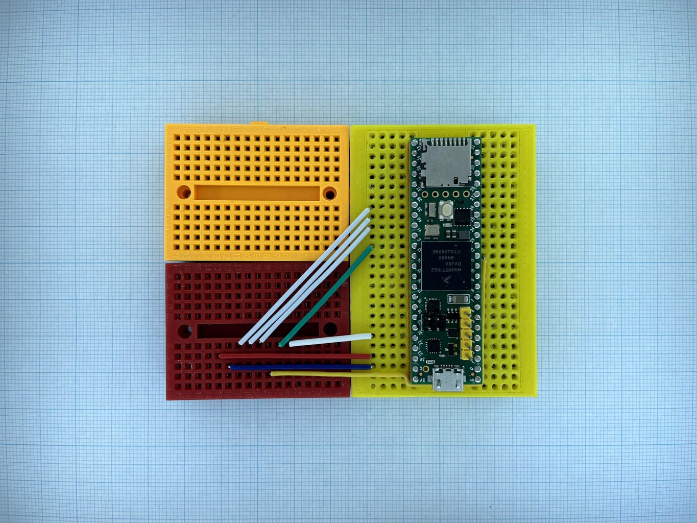

Connection summary:
Teensy 4.1    -> ILI9341
Vin           -> Vcc
GND           -> GND
GPIO 39       -> CS
GPIO 40       -> RESET
GPIO 41       -> D/C
GPIO 11(MOSI) -> SDI(MOSI)
GPIO 13(SCK)  -> SCK
GPIO 22       -> LED
Step 13: Arduino Nano
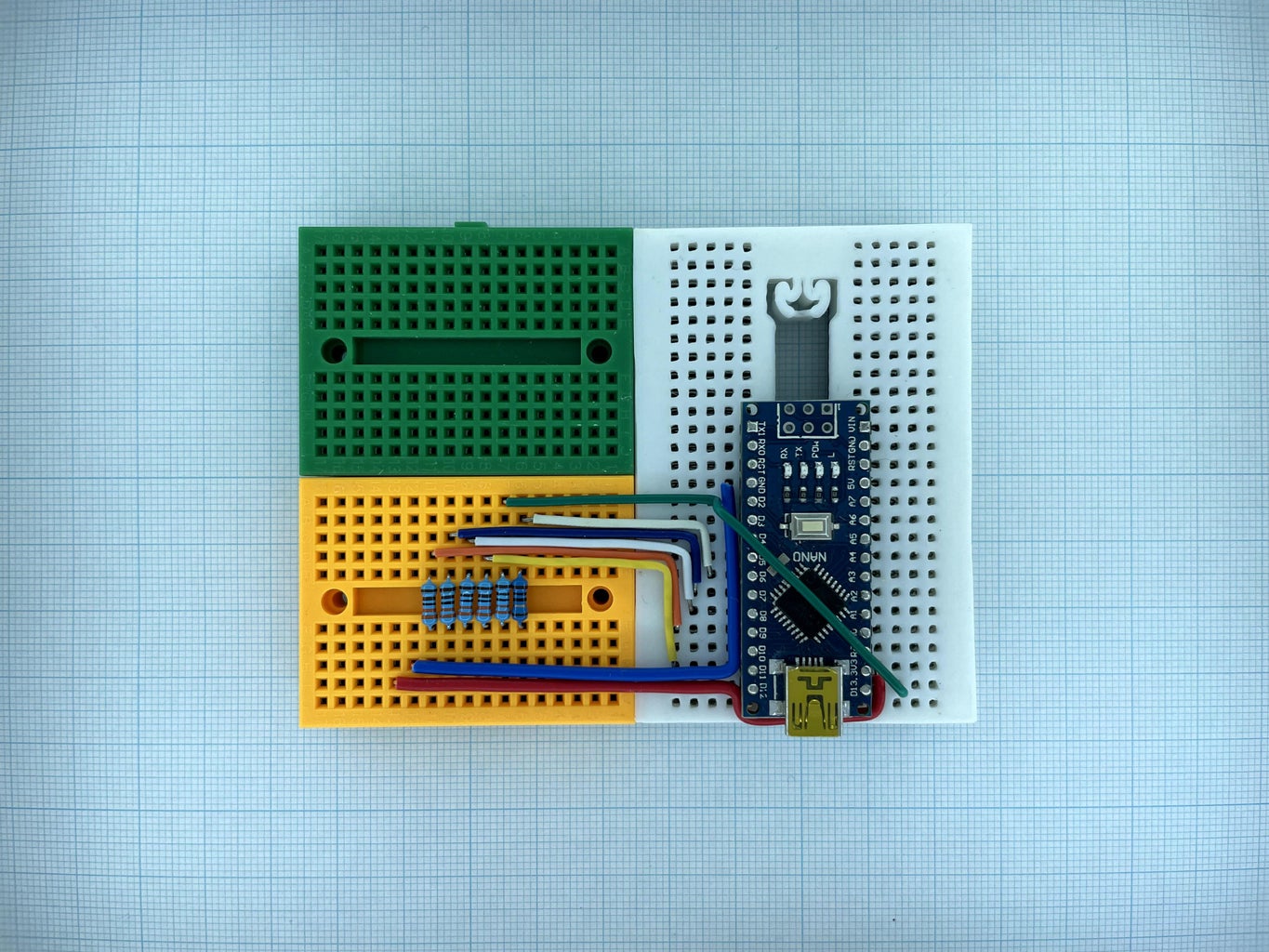

Since Arduino Nano is 5V dev board but most display is not 5V I/O tolerant so it require some resistors between GPIOs and display pins.
Connection summary:
Arduino Nano                   -> ILI9341
Vin                            -> Vcc
GND                            -> GND
GPIO 9        -> 3.3k resistor -> CS
GPIO 7        -> 3.3k resistor -> RESET
GPIO 8        -> 3.3k resistor -> D/C
GPIO 11(MOSI) -> 3.3k resistor -> SDI(MOSI)
GPIO 13(SCK)  -> 3.3k resistor -> SCK
GPIO 6                         -> LED
Step 14: Arduino Nano 33 BLE
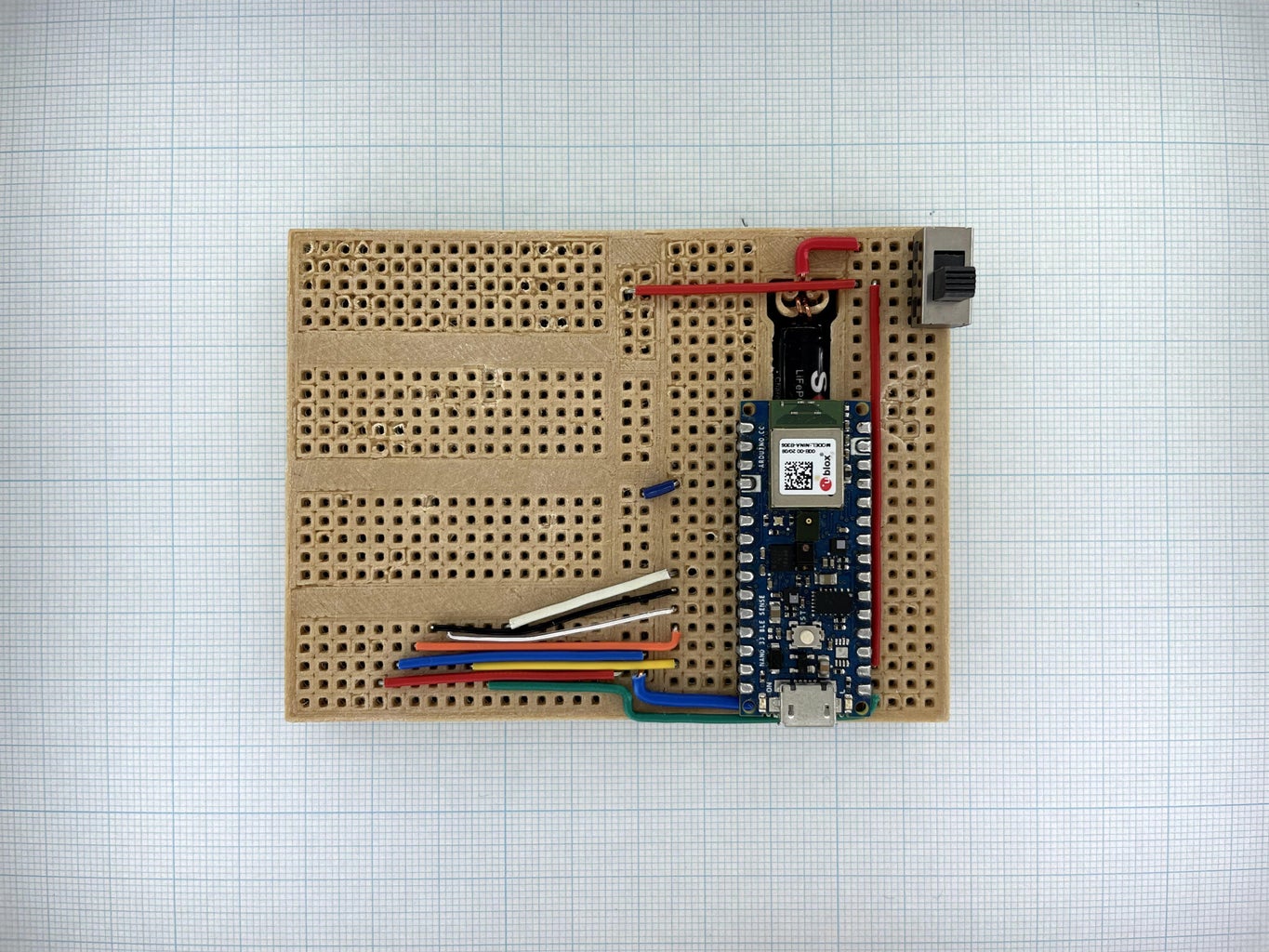

Connection summary:
Arduino Nano 33 BLE -> ILI9341
Vin                 -> Vcc
GND                 -> GND
GPIO 9              -> CS
GPIO 7              -> RESET
GPIO 8              -> D/C
GPIO 11(MOSI)       -> SDI(MOSI)
GPIO 13(SCK)        -> SCK
GPIO 6              -> LED
Step 15: Black Pill


Connection summary:
Black Pill    -> ILI9341
Vin           -> Vcc
GND           -> GND
GPIO A4       -> CS
GPIO A2       -> RESET
GPIO A3       -> D/C
GPIO A7(MOSI) -> SDI(MOSI)
GPIO A5(SCK)  -> SCK
GPIO A1       -> LED
Step 16: ESP8266


Connection summary:
ESP8266       -> ILI9341
Vin           -> Vcc
GND           -> GND
GPIO 15       -> CS
GPIO 2        -> RESET
GPIO 4        -> D/C
GPIO 13(MOSI) -> SDI(MOSI)
GPIO 14(SCK)  -> SCK
GPIO 5        -> LED
Step 17: Seeeduino XIAO


Connection summary:
Seeeduino XIAO -> ILI9341
Vin            -> Vcc
GND            -> GND
GPIO 3         -> CS
GPIO 1         -> RESET
GPIO 2         -> D/C
GPIO 10(MOSI)  -> SDI(MOSI)
GPIO 8(SCK)    -> SCK
GPIO 0         -> LED
Step 18: RTL8720DN


Connection summary:
RTL8720DN     -> ILI9341
Vin           -> Vcc
GND           -> GND
GPIO 18       -> CS
GPIO 2        -> RESET
GPIO 17        -> D/C
GPIO 21(MOSI) -> SDI(MOSI)
GPIO 19(SCK)  -> SCK
GPIO 23       -> LED
Ref.:
Step 19: ESP32


Connection summary:
ESP32         -> ILI9341
Vin           -> Vcc
GND           -> GND
GPIO 5        -> CS
GPIO 33       -> RESET
GPIO 27       -> D/C
GPIO 23(MOSI) -> SDI(MOSI)
GPIO 18(SCK)  -> SCK
GPIO 22       -> LED
Step 20: ESP32-C3
Connection summary:
ESP32-C3      -> ILI9341
Vin           -> Vcc
GND           -> GND
GPIO 7        -> CS
GPIO 1        -> RESET
GPIO 2        -> D/C
GPIO 6(MOSI)  -> SDI(MOSI)
GPIO 4(SCK)   -> SCK
GPIO 3        -> LED
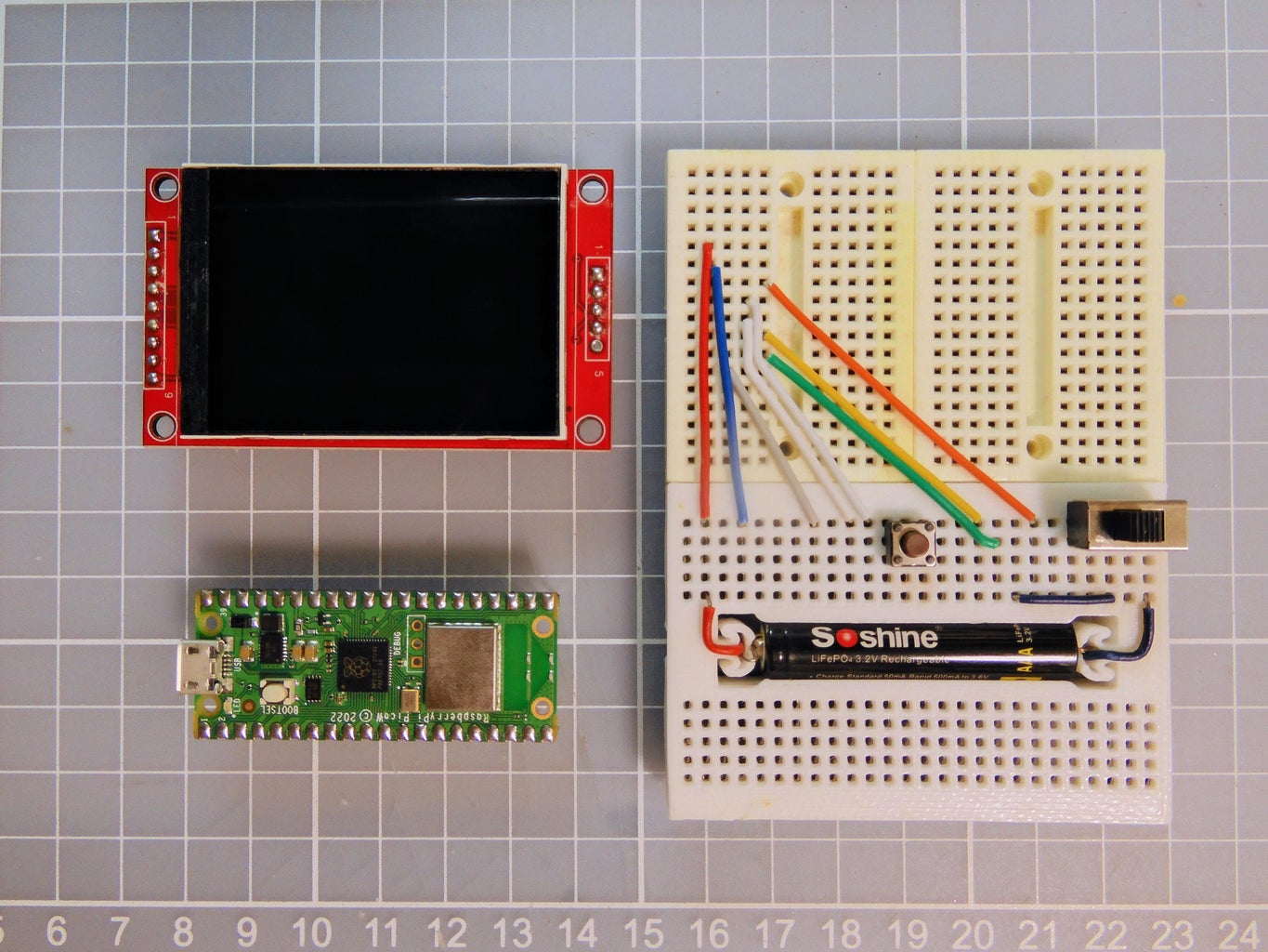
Step 21: Raspberry Pi Pico


Connection summary:
Raspberry Pi Pico -> ILI9341
Vin               -> Vcc
GND               -> GND
GPIO 17           -> CS
GPIO 26           -> RESET
GPIO 27           -> D/C
GPIO 19(MOSI)     -> SDI(MOSI)
GPIO 18(SCK)      -> SCK
GPIO 28           -> LED
Step 22: Raspberry Pi Pico W

Connection summary:
Raspberry Pi Pico -> ILI9341
Vin               -> Vcc
GND               -> GND
GPIO 17           -> CS
GPIO 26           -> RESET
GPIO 27           -> D/C
GPIO 19(MOSI)     -> SDI(MOSI)
GPIO 18(SCK)      -> SCK
GPIO 28           -> LED
Step 23: Data Bus
Arduino_GFX now support the following data bus:
- 8-bit and 9-bit hardware SPI (ESP32SPI)
- 8-bit hardware SPI (HWSPI, ESP8266SPI, mbedSPI, NRFXSPI, RPiPicoSPI)
- 8-bit and 9-bit software SPI (SWSPI)
- 8-bit parallel interface (AVRPAR8, ESP32PAR8, RPiPicoPAR8, RTLPAR8)
- 16-bit parallel interface (ESP32PAR16, RPiPicoPAR16)
More details at GitHub WiKi: https://github.com/moononournation/Arduino_GFX/wi...
I cannot mention all data bus class detail here, just highlight some special below.
9-bit SPI
9-bit SPI is not the most common name for this interface, a more common name is 3-line SPI or 3-wire SPI. But I found there have 2 different meaning for 3-line SPI:
- No DC pin, append 1-bit for each 8-bit data to represent it is command or data. 3-line is CLK, MOSI and MISO
- Combined MOSI and MISO pin, data input and output use same GPIO. 3-line is DC, CLK and MOSI+MISO
So I will avoid call 9-bit SPI as 3-line SPI.
In digital world, the smallest data size is bit, but the actual smallest data computation and storage size is byte (8 bit). So many MCU only can support transfer SPI data bit in the factor 8. I found ESP32 SPI can freely control the number of bit transfer, so I make ESP32SPI Data Bus class support 9-bit SPI.
Software SPI also can support 9-bit SPI, it just slower.
mbedSPI or NRFXSPI
The official SPI for Arduino Nano 33 BLE is a little bit slow for color display, it even much slower than Arduino Nano. It is a well known issue on the web, the reason may caused by a mbedOS in the middle. When I dig into the firmware source code, I found 9 internal classes related to SPI. I selected implement 2 classes. I think NRFXSPI implementation can meet the performance of 64 MHz main frequency, mbedSPI is just a backup plan in case NRFXSPI broken something in mbedOS.
Parallel Interface
AVR family is 8-bit MCU, running in 8 or 16 MHz, maximum SPI speed is 4 MHz. Seems not fast enough for color display, as show in the first video. How about 8-bit parallel? MCU can use port operation command direct access all GPIOs under same port in 1 instruction. So AVR 8-bit parallel interface (AVRPAR8) can run much faster than SPI. However, most AVR dev board not breakout enough pins for 8-bit port operation. E.g. Arduino UNO only break out port D all 8 GPIOs but use port D require sacrifice the serial port pins.
Many 32-bit MCU also have port operation, but the port also in 32-bit. It means require some bit operation before setting only 8-bit data (more than 1 instruction), so it is not as efficient as 8-bit MCU.
RPiPicoPAR16 data bus class utilize Raspberry Pi Pico 32-bit data port first 16 bits to form a 16-bit parallel interface, average only requires around 2 instructions to send 16 bits data, so it is very efficient.
ESP32PAR8, RTLPAR8 and ESP32PAR16 are actually a semi-software implementation of parallel interface, so it is not run very fast.
Step 24: AVR Port Patching
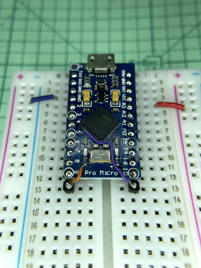

As mentioned in previous step, many AVR breakout board not breakout all port GPIOs and limited the port parallel interface usage. If you want challenge your soldering skill, you can breakout the missing pins yourself ;>
The above pictures and video are breakout Arduino Pro Micro 8MHz port B all pins and connect to NT35310 display.
Step 25: Display Driver
Arduino_GFX currently support below display:
- GC9A01 round display 240x240
- HX8347C 240x320
- HX8347D 240x320
- HX8352C 240x400
- HX8357A 320x480 (currently only portrait works, i.e. rotation 0 and 2)
- HX8357B (9-bit SPI) 320x480
- ILI9225 176x220
- ILI9341 240x320
- ILI9342 320x240
- ILI9481 320x480
- ILI9486 320x480
- ILI9488 320x480
- JBT6K71 240x320
- NT35310 320x480
- NT35510 480x800
- NT39125 240x376
- R61529 320x480
- SEPS525 160x128
- SSD1283A 130x130
- SSD1331 96x64
- SSD1351 128x128 and 128x96
- ST7735 80x160, 128x128 and 128x160 various tabs
- ST7789 135x240, 240x240, round corner display 240x280 and 240x320
- ST7796 320x480
All display class details are described at GitHub Wiki: https://github.com/moononournation/Arduino_GFX/wi...
You may find more display discussion in my previous instructables: https://www.instructables.com/Select-Color-Displa...
I cannot mention all display details here, just highlight some special below.
GC9A01
This is a round display with 240x240 resolution. Same as ILI9341, this display is not 5V I/O tolerant so it require some resistors between GPIOs and display pins if using 5V MCU like Arduino Nano.
#include <Arduino_GFX_Library.h>
Arduino_DataBus *bus = create_default_Arduino_DataBus();
Arduino_GFX *gfx = new Arduino_GC9A01(bus, 7 /* RST */, 0 /* rotation */, true /* IPS */);
HX8357B
This is an IPS display with 320x480 resolution. This display only support 9-bit SPI so it is better connect with ESP32SPI.
#include <Arduino_GFX_Library.h>
Arduino_DataBus *bus = new Arduino_ESP32SPI(-1 /* DC */, 5 /* CS */, 18 /* SCK */, 23 /* MOSI */, -1 /* MISO */);
Arduino_GFX *gfx = new Arduino_HX8357B(bus, 7 /* RST */, 0 /* rotation */, true /* IPS */);
NT35510
This is the highest resolution display I have in hand, it is 480x800. This display support 8-bit or 16-bit parallel interface.
#include <Arduino_GFX_Library.h>
Arduino_DataBus *bus = new Arduino_RPiPicoPAR8(27 /* DC */, 17 /* CS */, 18 /* WR */, 19 /* RD */);
Arduino_GFX *gfx = new Arduino_NT35510(bus, 7 /* RST */, 0 /* rotation */);
Step 26: Canvas
Arduino_GFX provide various canvas class, sometimes it call framebuffer, for draw buffering on complicated presentation:
- Canvas (16-bit color, 2 bytes for each pixel)
- Canvas_Indexed (half memory space)
- Canvas_3bit (1/4 memory space framebuffer)
- Canvas_Mono (1/16 memory space framebuffer)
The display only require refresh once after canvas draw finish and call flush(). It can reduce the display flicking substantially but requires more RAM.
First declare a canvas output display:
#include <Arduino_GFX_Library.h>
Arduino_DataBus *bus = create_default_Arduino_DataBus();
Arduino_GFX *output_display = new Arduino_ST7789(bus, TFT_RST, 0 /* rotation */, true /* IPS */);
Then declare canvas: (240x320 resolution requires 153600 bytes RAM)
Arduino_GFX *gfx = new Arduino_Canvas(240 /* width */, 320 /* height */, output_display);
Step 27: TFT 3-bit Driver
Some display support 3-bit color space like ILI9488. It is hard to direct implement 3-bit color space efficiently. But it can work with a Canvas_3bit class in the middle:
#include <Arduino_GFX_Library.h>
// 3-bit color Canvas, R1G1B1, 8 colors
Arduino_G *output_display = new Arduino_ILI9488_3bit(bus, -1 /* RST */, 0 /* rotation */, false /* IPS */);
Arduino_GFX *gfx = new Arduino_Canvas_3bit(480 /* width */, 320 /* height */, output_display);
Step 28: Supported Dev Device

Arduino_GFX support create default display class accordingly to selected built-in display dev device in Board selection menu. Below are recognizable dev device:
- Wio Terminal
- M5Stack Core Family (v1)
- Odroid Go
- TTGO T-Watch
Simple declaration:
#include <Arduino_GFX_Library.h>
Arduino_GFX *gfx = create_default_Arduino_GFX();
Step 29: More Dev Device
You may find PDQgraphicstest have more dev device setting example.
Step 30: Examples

Arduino_GFX have few examples demonstrate how to use this library:
(Arduino IDE File menu -> Examples -> GFX Library for Arduino)
- AsciiTable - show all default font characters in table format
- Clock - A simple non-flicking analog clock implementation
- Hello World - Everyone first display program
- HelloWorldGfxfont - more fonts
- ImgViewer - display Animated GIF, BMP, JPEG, MJPEG or PNG image files from flash file system or SD card
- LVGL - Demostrate the LVGL implementation with Arduino_GFX
- MultipleDeviceTest - connect multiple display at the same time
- PDQgraphicsTest - you can find many GFX functions demo here
- WiFiAnalyzer - A simple WiFi Analyzer for WiFi capable platform
- WiFiPhotoFrame - Download photo on the web and display on the fly
Step 31: More Application

Here are my previous instructables using Arduino_GFX:
- https://www.instructables.com/Game-MINTIA/
- https://www.instructables.com/Arduino-NES/
- https://www.instructables.com/Dual-Band-WiFi-Analy...
- https://www.instructables.com/Portable-IoT-Display...
- https://www.instructables.com/Play-Video-With-ESP3...
- https://www.instructables.com/Google-Photo-Clock/
- https://www.instructables.com/Floating-Display/
- https://www.instructables.com/COVID-19-WHO-Dashboa...
- https://www.instructables.com/Face-Aware-OSD-Photo...
- https://www.instructables.com/Servo-Tester-2/
- https://www.instructables.com/Arduino-BiJin-ToKei/
- https://www.instructables.com/Arduino-Watch-2/
- https://www.instructables.com/Arduino-Watch-Core/
- https://www.instructables.com/TTGO-T-Watch/
Runner Up in the
Arduino Contest


![Tim's Mechanical Spider Leg [LU9685-20CU]](https://content.instructables.com/FFB/5R4I/LVKZ6G6R/FFB5R4ILVKZ6G6R.png?auto=webp&crop=1.2%3A1&frame=1&width=306)


