

Introduction: Arduino Servo Shield


This instructable explains how to make an “Arduino Servo Shield” from a PCA9685 breakout module and an Arduino PCB expansion board.
The basic module supports 16 servos which may be expanded to 992 servos by adding additional PCA9685’s.
Images
- The cover photo shows five servos attached to the PCA9685 servo shield
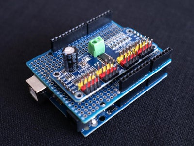
- Photo 2 shows the PCA9685 Servo Shield attached to an Arduino UNO R3
- The PCA9685 Servo Shield video shows the five servos in operation [1]
- The PCA9685 Servo Plotter video shows an experimental servo plotter attached to the shield [2]
Notes:
[1]
- The code used in both videos is provided in Step 3 “Software”
[2]
- Construction details for the servo plotter may be found here https://www.instructables.com/Servo-Plotter/
- The wobbles in the radial lines are due to mechanical backlash in the servos.
Supplies
The following items were obtained from https://www.aliexpress.com/
- 1 only Arduino UNO R3 + USB cable
- 1 only PCA9685 16 Channel 12-bit PWM Servo Module
- 1 only prototype PCB expansion b oard for Arduino UNO R3 Shield
The following items were obtained locally:
- Hookup wire
- Breakable male header strip pins
The estimated cost of this project is less than $50.00
Step 1: Theory
The PCA9685 I2C breakout module has its own clock.
Each module supports 16 servos.
Up to 62 modules may be daisy chained for a total of 992 servos.
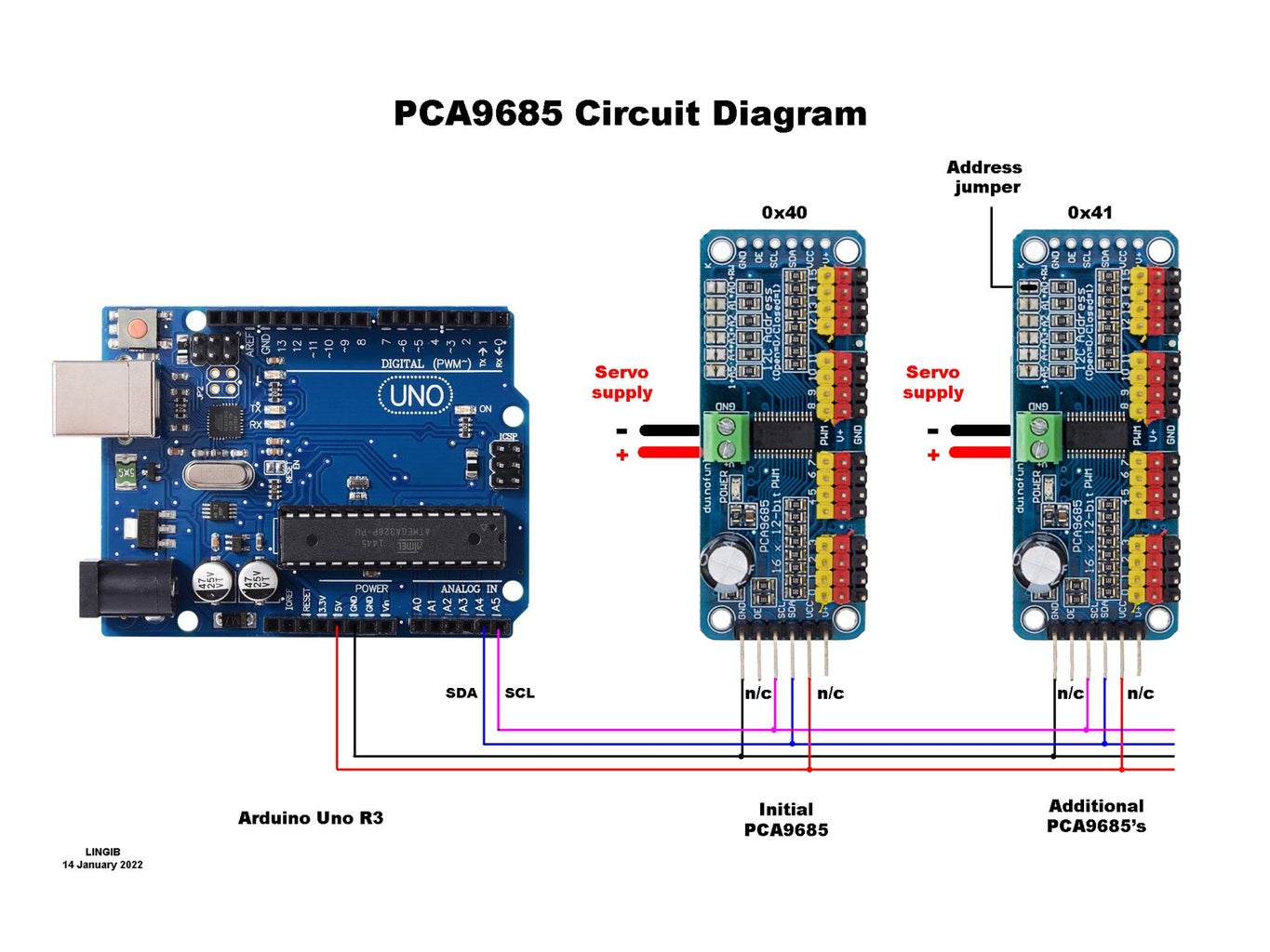
The V+ pin on each module is connected directly to the green connector. Connect it to the Vin pin of your Arduino for self-contained operation if your servo supply is between 7V~12V.
The default address for each module is 0x40.
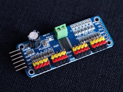
Additional modules require that you jumper the address lines by means of a solder blob(s) as shown in photo1
The PCA9685 modules may also be connected in a serpentine manner as shown here https://learn.adafruit.com/16-channel-pwm-servo-driver/chaining-drivers. This method is probably intended for small pockets of servos as all of the servo current passes through the PCB wiring rather than the load being spread as shown in photo 1.
Step 2: Construction


Step 1
- Solder the header pins shown in photo1 to the Arduino expansion board
Step 2
- Replace (unsolder) the existing pins on the PCA98685 Servo module with breakable single-line male header pins. The pins are shown in photo 2.
- Fit a second set of breakable single-line male header pins at the opposite end.
Step 3
- Position the PCA9685 module such that the pins do not touch the Arduino connectors beneath and solder in position as shown in photo 3
Step 4
Wire the
- Arduino 5V to the PCA9685 VCC
- Arduino GND to the PCA9685 GND
- Arduino SCL (pin A5) to the PCA9685 SCL
- Arduino SDA (pin A4) to the PCA9685 SDA
These connections are shown in photo 4
Step 3: Software


Step 1
- Download and install the Arduino IDE (Integrated Development Environment” from https://www.arduino.cc/en/software.
Step 2
- Download and install the following library https://github.com/adafruit/Adafruit-PWM-Servo-Driver-Library
- This library may also be installed by clicking “Tools/Manage Libraries” in your Arduino and typing “adafruit pwm” in the search bar as shown in photo 1.
- This method requires some patience as it takes a while before anything happens. Click “Install” when the library listing appears.
Step 3
- Download the attached file “PCA9685_servo_demo.ino” and copy the contents into a fresh Arduino sketch. Use a text editor such as Notepad++ ... not a word processor.
- Save the sketch as “ PCA9685_servo_demo” without the quotes then compile and upload it to your Arduino.
- Disconnect the USB cable to your Arduino
- Attach your servos to the shield ... observe the color codes
- Attach the shield to your arduino
- Reinsert the USB cable into your PC
- Apply power (typically 5V~6V) to the green connector ... your servos should start cycling.
Step 4
- Assuming that you have constructed my Servo Plotter described in https://www.instructables.com/Servo-Plotter/ download and install the attached file “PCA9685_servo_plotter.ino”.
- Save the sketch as “PCA9685_servo_plotter” without the quotes then compile and upload it to your Arduino.
- Disconnect the USB cable to your Arduino
- Connect the “shoulder” servo to shield position 0 ... observe the color codes
- Connect the “elbow” servo to shield position 1 ... observe the color codes
- Connect the “pen-lift” servo to shield position 3 ... observe the color codes
- Attach the shield to your arduino
- Reinsert the USB cable into your PC
- Apply power (typically 5V~6V) to the green connector
- Launch the Arduino Serial Monitor at 115200 bauds
- Select option T5 from the menu shown in photo 2 ... the plotter should start drawing a set of radial lines. A video in the Intro section shows this plotter in operation.
WARNING
Keep clear of the servo arms at switch-on. The servos are extremely powerful and present a crushing hazard if the servos horns are in the wrong position.

Step 4: Summary
- This instructable explains how to make an “Arduino Servo Shield” from a PCA9685 breakout module and an Arduino PCB expansion board.
- The basic module supports 16 servos which may be expanded to 992 servos by adding additional PCA9685’s.
- The estimated cost of this project is less than $50.00
Click here to view my other instructables.

Participated in the
Anything Goes Contest 2021

![Tim's Mechanical Spider Leg [LU9685-20CU]](https://content.instructables.com/FFB/5R4I/LVKZ6G6R/FFB5R4ILVKZ6G6R.png?auto=webp&crop=1.2%3A1&frame=1&width=306)


