

Introduction: Automated Chessboard


Welcome,
I like playing chess game and up to now I played a lot on the Internet or with different Apps. But I was frustrated to pass all this time behind a screen.
I started to look into the electronic chess games, but I rapidly realize that the best choice was to do it by myself. I took time to learn about AI, game engine, chess pieces detection to finally design my own chess game.
So, this Instructable describes an automated chessboard with two game modes. The first one, Human vs Human, with a control of the chess pieces displacements. The second one, Human vs Computer, with an automatic chess pieces movement for the computer player. The computer player chess pieces have a phantom displacement thanks to a hidden moving mechanism.
The automated chess board is composed of an XY table with an electromagnet on the moving trolley. The chessboard is placed above the XY table and the chess pieces are equipped with magnets. When the electromagnet is below the chess piece a magnetic contact can be generated through the chessboard, so that the chess piece follows the trolley when it moves.
LCD screen and arcade buttons are added to interact with the players (select the game modes, timer control, inform about the events…)
- Overall dimensions : 460mm x 460mm x 100mm
- Chess pieces size : Staunton 3
- Programming Language : Arduino C/C++
- Powering : 12V / 2A
Step 1: Parts List


XY table :
- 2 x V slot 20x20 linear rail, Length = 345 mm
- 1 x V slot 20x20 linear rail, Length = 315 mm
- 1 x V slot 20x20 linear rail, Length = 350 mm
- 1 x V slot 20x20 linear rail, Length = 395 mm
- 10 x 90 degree Corner Bracket
Transmission :
- 2 x GT2 Pulley, 20 teeth, 5mm bore
- 8 x GT2 Toothless pulley
- 3.5m x GT2 Belt
Electronics :
- 1 x Arduino Nano
- 2 x Stepper Motor - Adafruit - Nema 17 size - 200 steps/rev, 12V 350mA
- 2 x Stepper Motor Driver Carrier - Pololu - A4988
- 1 x LCD Module - I2C Serial - 2.6“
- 2 x Arcade button - Bore hole 23.5 mm
- 1 x Electromagnet - 5Kg Holding Force
- 1 x Freewheeling diode - 1N4001
- 1 x Power Transistor - TIP 120
- 2 x Micro Limit switch roller
- 64 x Reed Switch - Dia 2 x 14.5 mm
- 1 x Resistor - 1K ohm
- 4 x MUX breakout - SparkFun - CD74HC4067
- 1 x Terminal Block - DC Jack
- Female Headers
- 10 x Screw Terminal
- 3 x Prototyping Board - 50 x 100 mm
- 4 x HE10 Connectors
- 8 x Ribbon Cable - 8
Chess :
- 1 x Chess pieces set - Staunton 3
- 1 x Chessboard Sticker - Squares size : 37 x 37 mm
- 32 x Magnet, Dia 8 x 3 mm
Box :
- 1 x Foamboard - 462 x 462 x 5 mm
- 1 x Foamboard - 462 x 462 x 10 mm
- 2 x Foamboard - 462 x 80 x 10 mm
- 2 x Foamboard - 442 x 80 x 10 mm
Bolting :
- 8 x Mini V Wheel
- 4 x Aluminium Spacer - ID : 5mm - Height : 6mm
- 4 x Eccentric Spacer - M5
- 4 x Hex. Locking Nut - M5
- 4 x Thin Hex. Nut - M5
- 8 x Mini Precision Shim - OD : 8 mm - ID : 5 mm - Thickness : 1 mm
- 26 x T-Nuts - M5
- 14 x Hex. Socket Button Head Cap Screw - M5 x 8 mm
- 12 x Hex. Socket Button Head Cap Screw - M5 x 12 mm
- 2 x Hex. Socket Button Head Cap Screw - M5 x 35 mm
- 2 x Hex. Socket Button Head Cap Screw - M5 x 30 mm
- 2 x Hex. Socket Button Head Cap Screw - M5 x 25 mm
- 8 x Hex. Socket Button Head Cap Screw - M5 x 15 mm
- 4 x Slotted Head Screw - M2 x 15 mm
- 4 x Nut - M2
- 8 x Hex. Socket Head Cap Screw - M3 x 10 mm
- 1 x Hex. Socket Head Cap Screw - M4 x 15 mm
- 4 x Slotted Countersunk Head Screw - M5 x 20 mm
- 4 x Nut - M5
3D Model :
All the structural parts were designed for 3D printing.
Step 2: XY Table


Presentation :
The XY table performs the displacements of the electromagnetic trolley (described on the next step). The XY table is composed of two motorized linear slides, one for the X axis motion and one for the Y axis motion.

Description :
The main functionalities of the linear slides (guiding and moving) are inspired by the 3D printer universe.
- Guiding :
The guiding of the linear slides is based on the V-slot concept. The V-slot design uses standard aluminum profile with a V machining at the central grooves, to allow the centering of a specific wheels. The beam is acting like a linear rail when the wheel is seated into the V groove.

The main advantage of these beams is to combine two functionalities, provide rigid supports for the frame structure and linear rails for the guiding of the wheels.
For the X displacement, the guiding is performed by means of 4 wheels, two at each extremity of the lateral beams.

For the Y displacement, the guiding is performed by means of 4 wheels as well, two on each side of the trolley beam.

For a proper functioning of the sliding, the contact force or gap between the wheels and the beams is essential. If the gap is too tight, the sliding will be difficult and if it is too slack, the guiding will be not accurate.
It is impossible to obtain the good contact force only from construction, so a set up system shall be implemented. Eccentric spacers are used to set the good gap adjustment between the wheels and the beams. Turning the eccentric spacers increases or decreases the gap and will give the best compromise between the guiding and the sliding.

Exploded view of wheels arrangement:

- Moving :
The trolley motorization is based on the Core XY concept. Two motors with two belts are used to move the trolley following the X and Y axes.
The main advantage of the Core XY concept compared to cartesian kinematics is to avoid having a motor on board the trolley beam. Thus, the horizontal beam is more compact and allow to have a bigger working envelope.

The Core XY requires more attention, the belts arrangement is more complex and there are more pulleys to align. But the automated chessboard does not need the same accuracy than a 3D printer.
How it works :
If only one motor turns a diagonal displacement will be generated. Changing the motor rotation direction will give an inverted displacement.
If two motors turn in the same direction a horizontal displacement will be generated.
If two motors turn in opposite directions a vertical displacement will be generated.

CW : Clockwise / ACW : Anti Clockwise
At the start-up, the X & Y coordinates of the trolley will be unknown, so at each commencement, the system needs to set the 0 for the X and Y axes. The setting consists in moving the trolley following the X and Y axes up to limit switches. The limit switches are fixed to the frame so that at each new start the 0 will be at the same location.

Step 3: Electromagnetic Trolley


Presentation :
The trolley is assembled on the XY table. It is equipped with an electromagnet. The electromagnet can generate a magnetic field which creates the link between the trolley and the chess pieces. So, when the trolley moves the chess pieces follow it.
Description :
An electromagnet is a type of magnet which produces a magnetic field from an electric current. The main advantage of an electromagnet compared to a permanent magnet is that the magnetic field is on demand. The electromagnet creates a magnetic field only if an electric current run through it, if the electric current is turned off the magnetic field stops.
The Arduino cannot directly power the electromagnet with its output pins because they cannot deliver enough power. So, the electromagnet must be connected to an independent electric current. A power transistor component piloted by the Arduino is used as a switch to power the electromagnet when needed. The advantage of the power transistor is that a low amperage is enough to control it, so it can be piloted by the Arduino.
Power transistor :

The power transistor is used like a switch. If it receives a low power to the pin B (Base), it allows the current to flow through the pin C (Collector) to the pin E (Emitter).
Step 4: Chessboard


Presentation :
The role of the chessboard is of course to represent the 64 black and white squares but not only. It also needs to localize the chess pieces position and interact with the human player.
Description :
- Chessboard :
Standard chessboards are made of high density wooden material and a high thickness, which can heavily disturb the electromagnetic field.
Foamboard material was preferred. It is easier to model, has a good flatness and does not disturb the magnetic field so much. A foamboard sheet of 5mm thickness was used.
A chessboard sticker was applied on it to materialize the chess squares. You could find on the internet some chessboard stickers on demand with your own dimensions.
- Localization of chess pieces :
The chess pieces localization is essential. The objective is to inform the software of the displacement of the human player chess pieces.
Magnetic sensors are placed below each chess piece square. So, when the magnet of the chess piece is above the sensor, the sensor will be activated. By comparing the activated sensors before and after the move, the chess piece displacement can be determined.
The magnetic sensor or Reed switch is composed of a hermetic glass envelope with two flexible metal contacts inside. The contact is normally open when there is no magnetic field and close if a magnetic field is present.

The 64 chess squares must be equipped with the sensors to be sure to properly monitor and avoid missing any displacements.
That means 64 sensors, which is impossible to connect all of them directly to the Arduino Nano, there are simply not enough pins on the boards. Multiplexers are used to increase the Arduino pins. The multiplexers are described in step 7.
- Game interface :
Arcade buttons and LCD screen are placed on the chessboard to interact with the players. They allow to set the game modes and specify if the moves are not authorized.
They allow to manage the countdowns time too, 10min are allocated for each player. Each player must press his button at the end of his turn. So, his countdown is stopped and the countdown of the opponent is started.
Step 5: Box

Presentation :
The box allows to hide the mechanism, give a good esthetic and fix the distance between the electromagnet and the chessboard.
Description :
Nothing complicated, just some foamboard sheets of 10 mm thick are assembled to form a box.
Foamboard was preferred for its ease of being constructible.
The height of the box walls is important, it fixes the distance between the electromagnet and the chess pieces magnet. Depending on your setup and material selection you need to investigate the good distance to allow a good magnetic field interaction and allow the chess pieces to move.

A hole on one wall is added to plug the power supply connector.
Step 6: AI - Artificial Intelligence

Presentation:
In human Vs human mode, the software will check that the moves are authorized and for the human vs computer mode, the software needs to decide what will be the next best moves. An AI (Artificial Intelligence) algorithm is used to make the decisions.
Description:
The AI proposed by this Instructable is based on an existing one. There are several efficient AI chess programs available on the internet.
For this project, the Micro Max chess program from H.G. Muller and ported for Arduino by Diego Cueva was preferred. It is a very smart, efficient and it is particularly small (<2kB).
The other main advantage is this program being an open source, so we can freely play with it, special THANKS to H.G. Muller & Diego Cueva.
The principle of this program is based on Minimax (or MinMax) and Alpha-Beta algorithms.
- Minimax:
The Minimax algorithm works exactly like a human brain. When it is its turn to play, the AI will analyze all its next possible moves. Evaluate all the possible answers from the Human player and what will be his answers etc., etc.
This analysis can be represented by a decision tree graphic:

This graphic does not represent a real chess game, there are so many boxes to show, it is a simplified version.
At the top (A), the current chess piece position to analyze and the aim is to define what is the best move to play (B1 or B2).
Each blue box (B, D) represents all the possible moves for the AI and each green box (C, E) all the possible moves for the human.
How it works :
The bottom boxes (E) are rated by an evaluation function which will attribute a value to them. The rating is calculated depending on the following criteria :
- Remaining chess pieces values
- Chess pieces positioning
- Isolated pawn
- Check or checkmate position
The objective of the evaluation function is to rate the current chess pieces position in the aim to know if the position is advantageous or not. Higher the rating is, better the AI has a chance to win.

After the evaluation of all the bottom boxes, their ratings go up the tree structure.
For the computer player turn, the AI will retain the max value, which Maximize its chance to win. And for the human player turn, the AI will consider that the human will play his best move so it will retain the min value, which Minimize the AI chance to win. Hence the name of Minimax.
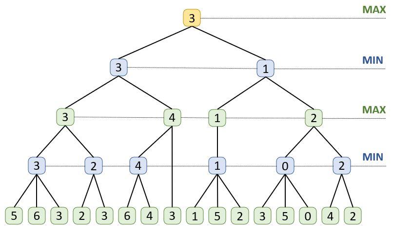
The rating of the E3 boxe is go up to the box A, so the best move to play for the AI is B1.
For a few moves to evaluate and a low game depth (like tic-tac-toe game), this algorithm is pertinent. But for a chess game with a lot of moves to evaluate and with a higher game depth, the required processor resources to evaluate all the possibilities are not possible with an Arduino board.
We need to prune the branches and it is the role of the Alpha-Beta algorithm.
- Alpha-Beta:
It is not necessary to evaluate all the branches of the decision tree. If the rating of one box is not pertinent, there is no reason to continue to evaluate the rest of that branch. It is exactly the role of the alpha-beta algorithm, it is to prune the decision tree.
For example, let us focus on the interest to evaluate the position E5 of the above decision tree graphic.
The brother of the position E5 is the position E4, they are in the same branch. Their parent D2 will select the Min, so if the position E5 is evaluated above 2, it will not be retained and if it is below 2, it will be retained. So, whatever the value of the position E5, we can be sure that the rating of D2 cannot be above 2.
In addition, the grandparent C1 of the positions E4 and E5 is also the grandparent of the positions E1, E2, E3, and it will choose the Max of his two children D1 and D2.
So, to change the value of the grandparent C1, the second brother D2 must be superior to the first brother D1. And it cannot be the case because D2 cannot be above 2.
So, it is not necessary to continue to evaluate this branch.

All the gray boxes are not necessary to be explored.
The Alpha-Beta algorithm compares all the branches in the aim to prune the decision tree and reduce the calculation time.
Step 7: Wiring

Motor:
The stepper motors used are bipolar, which means that they need a double H bridge circuit to power alternatively their coils. The A4988 Stepper Motor driver board was selected to control the motors.
Switch:
The arcade buttons and limit switches are connected to the Arduino with the internal pull up resistors. The arcade button A and the X limit switch are connected to the same pin, same for the arcade button B and the Y limit switch. The pin number available is limited so two pins are used for 4 switches. The arcade buttons and the limited switches are not used at the same time, so there is no risk of confusion.
Electromagnet:
Power transistor is used as a switch to pilot the electromagnet and free-wheeling diode is used to protect the Arduino from the discharging current, see step 3.
Screen:
The LCD screen is connected via the I2C (Inter Integrated Circuit) communication, in the aim to limit the pin number used, only two pins are necessary to communicate with the screen (SCL and SDA).
It means for the Arduino nano board, the SCL line shall be connected to the A5 pin and SDA line to the A4 pin.
Reed Switch:
There are 64 reed switches, it is impossible to connect them directly to the Arduino board, there are not enough pins available. Multiplexers are used to increase the pin number. Only 9 pins are necessary to connect the 64 reed switches.
One multiplexer can control 16 sensors, so 4 multiplexers were used for the 64 sensors.
The reed switches are connected to the multiplexers by means of channel pins (C0 to C15). Each channel pin has a specific 4-bit binary address. For example:
- C0 = 0000
- C1 = 0001
- C4 = 0100
- C10 = 1010
The four select pins (S0 to S3) allow to activate the channel. Meaning that, if S0=0, S1=1, S2=1 and S3=1 the channel C7 will be activated. In case you do not realize why 0111 corresponds to 7, it is may be time to review how to count in binary ;).
Once the channel is selected, its signal of the reed sensor can be recovered by means of the pin SIG.
So, to know the status of all the sensors, the first multiplexer is activated, all the channels are explored and the multiplexer is switched off. The second multiplexer is activated, all the channels are explored, and so on for the other multiplexers.

Step 8: Code

Presentation:
The code drives all the actions of the Automated Chessboard. Interact with players, detect the human player moves, compute the AI moves and control the XY table motors.
Description:
- General :
This instructable is based on the Arduino environment and the C language, if you are not familiar with them, you need to take time to train you. They are a lot of efficient Instrutables and tutorials on Internet to help you.
To use the code, you need to install these two libraries:
- Wire.h
- LiquidCrystal_I2C.h
For a better readability, the global variables and the AI were placed on separate files.
- Global.h
- Micro_Max.h
- Micro_Max.cpp
- AI:
The proposed AI is based on the Minimax concept, see step 6.
The AI code is extremely optimized, all the variables have one character name, so for the variables meaning click on this link.
Human player moves detection:
The IA needs to know the human players displacement to perform its calculation. For that it needs to know the departure coordinates and the arrival coordinates of the move.
The coordinates are defined by a letter for the column and a number for the line.
For example, displacement of the central white pawn: e2e4

Chess game representation of the serial monitor
(Capital letter for white player and lowercase letter for black player)
To determine the displacement of the human player, the code compares the status of the reed switches before and after the move. For the above example (e2e4), the reed switch mappings will display:

The reed switches are connected by means of the internal pull up of Arduino, it means that for the chess piece presence the sensor indicates 0 and 1 if there is no chess piece.
So, if a 0 becomes 1 it means departure of the move and if 1 becomes 0 it means arrival.
- XY Table:
The departure square and the arrival square of the move are defined. For the above example (e2e4), the horizontal displacement will be 0 because the departure and the arrival are in the same column (e). And the vertical displacement will be of 2 squares because there are 2 squares of difference between the departure (2) and the arrival (4). So, the direction and the distance are known, the motors can be activated.
Special moves:
Some chess pieces movements need to cross other chess pieces, like a bishop and castling displacements. To avoid any contact between the chess pieces, the displacement path imposes to move between two squares and not to the middle.

Same for the capturing. A captured piece is pushed out of the chessboard, this displacement follows the intersection of two squares and do not pass through the middle of the squares.


Step 9: Assembling


XY Table & Trolley :
- Assemble the trolley
- Slide the trolley to the trolley beam. Adjusted the friction gaps with the eccentric spacers in the aim to obtain an easy sliding. Assemble and add the two pulley supports at each extremity of the trolley beam
- Assemble the main frame. Ensure to have a good parallelism between the beams.
- Assemble the pulley supports
- Slide the trolley beam to the main frame and set the friction gaps. Add the pulley supports
- Add the stepper motors
- Add the belts. Adjust the bels length to have a good driving by the motors, again it is a compromise between too much tension and too much slack.

Chess Board :
- To the top face, place the sticker and cut the holes for the arcade buttons and the lcd screen
- To the bottom face, draw the chessboard corresponding to the top face in the aim to have the chessboard squares to the bottom face at the same location that the top chessboard squares
- Assemble the 8 sets of the 8 reed switches by means of ribbon cable. The distance between the reed sensors shall be corresponding to the chessboard square size.
- Glue the reed switches sets, add the arcade buttons and the lcd screen
- Finalize the wiring

Chess pieces :
- Removed the bottom felt
- Glue the magnet and its support inside the chess pieces

Box :
- Cut the walls following the dimensions given to the step 2, take care to have a good parallelism of the sides of the walls
- Assemble the walls with glue

Electronic :
- Assemble the prototyping boards
- Place the headers and the connectors
- Glue the prototyping boards to their supports. Solder the headers, connectors and the wires following the wiring schema, see step 8
- Place the boards to their supports

Step 10: Conclusion

Playing chess online brings a lot of advantages, you could play anytime, with a lot of different players (human or AI), record the game and take time to analyze it. But playing real chess brings another vision of the game, a different experience. Be not behind a screen, touch the chess pieces, have 3d vision allow to think differently.
This Instructable proposes to combine the advantages of these two worlds, take the benefits of the digital model and the advantages of playing real chess with an additional funny touch for the phantom displacements.
Moreover, the AI proposed for this Instructable is powerful but limited due to the Arduino board performances. But it is possible to add a more powerful computation system with a Raspberry board or with a PC.
Other useful feature, you could create your own AI or improve the existing one by adding some functionalities. For example, I like the Scotch opening, so I have added several releases of this opening into the AI (the 6 first moves are randomly selected among various Scotch openings and the AI takes the relay for the rest of the game) in the aim to practice and improve my understanding.
I truly hope this Instructable will inspire you & give you the desire to be creative.
Do not hesitate to contact me if you have any questions.
ENJOY!

First Prize in the
Toys and Games Contest

![Tim's Mechanical Spider Leg [LU9685-20CU]](https://content.instructables.com/FFB/5R4I/LVKZ6G6R/FFB5R4ILVKZ6G6R.png?auto=webp&crop=1.2%3A1&frame=1&width=306)


