

Introduction: Build a Transformable Hovercar! | Remote Control! | Part 1 (How To)


In part one of this project, I will show you how to build an awesome remote-controlled car that has the ability to redirect its blades.
For the best quality read, check out this article on my homepage here. If there's a pop-up, just simply click dismiss at the bottom. Also, don't forget to subscribe for free to support my work! :)
Step 1:
A Quick Preview
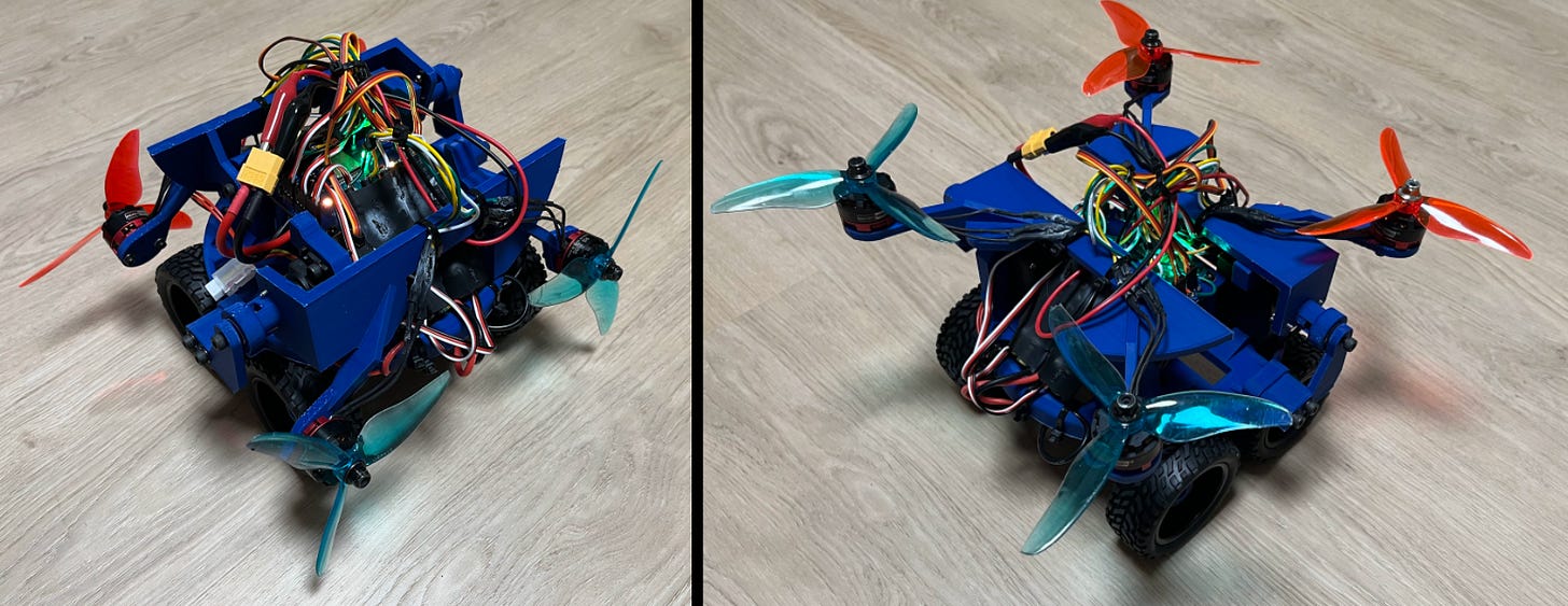
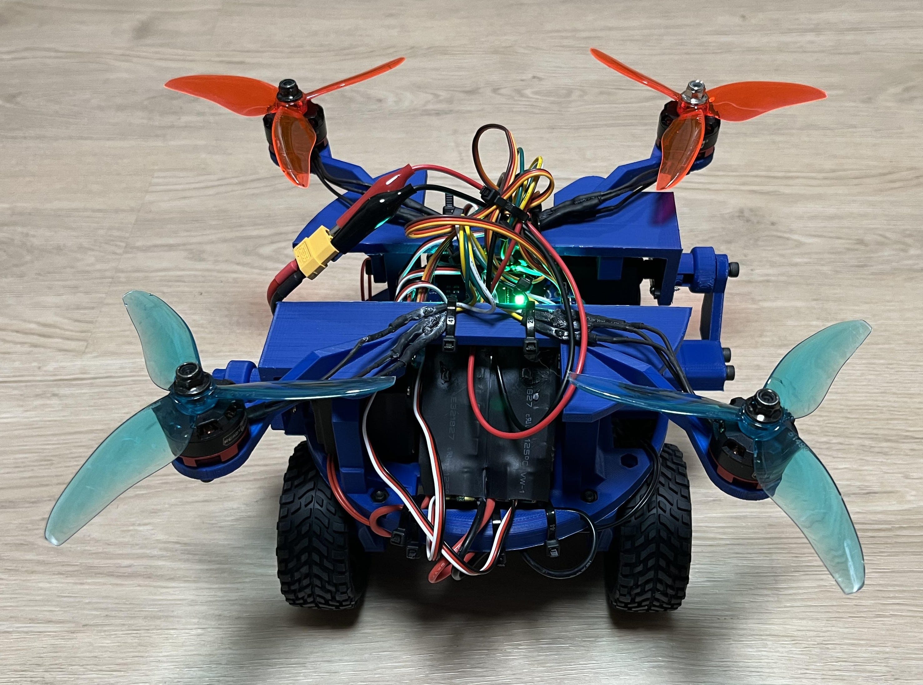
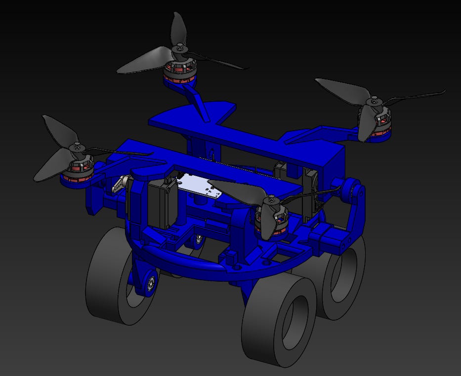
This is part one of my hovercar project! It uses four BLDC (brushless direct-current) motors to spin four propellers at a very high angular velocity, all while moving in combination with two servo motors to redirect the thrust from the propellers. This allows me to either drive it along the floor like a car or take it to the skies (in part two)! You could even say that this gives thevehicle the power to move three-dimensionally. I suppose I just decided that 2D is for squares (get it)?
Since this is only part one, I don’t yet have stable flight working. Even thoughthe hardware is finished and would work for flight, turns out, there’s A LOT more that goes into writing flight control software than meets the eye. Sure I could buy an off-the-shelf module, but that’s cheating! I’ve already invested a lot of time into this project, and want to start building some other cool things! That being said, I’ve decided to come back to this project and develop better flight control software (that doesn’t always break things) in a later project (part two). In the meantime…
Here’s a quick preview:
Step 2:
I am aware the car itself isn’t actually “hovering” when it’s being driven on the ground, but calling it a hovercar is way cooler than calling it a “transformable land airboat” so that’s what I’ll be doing.
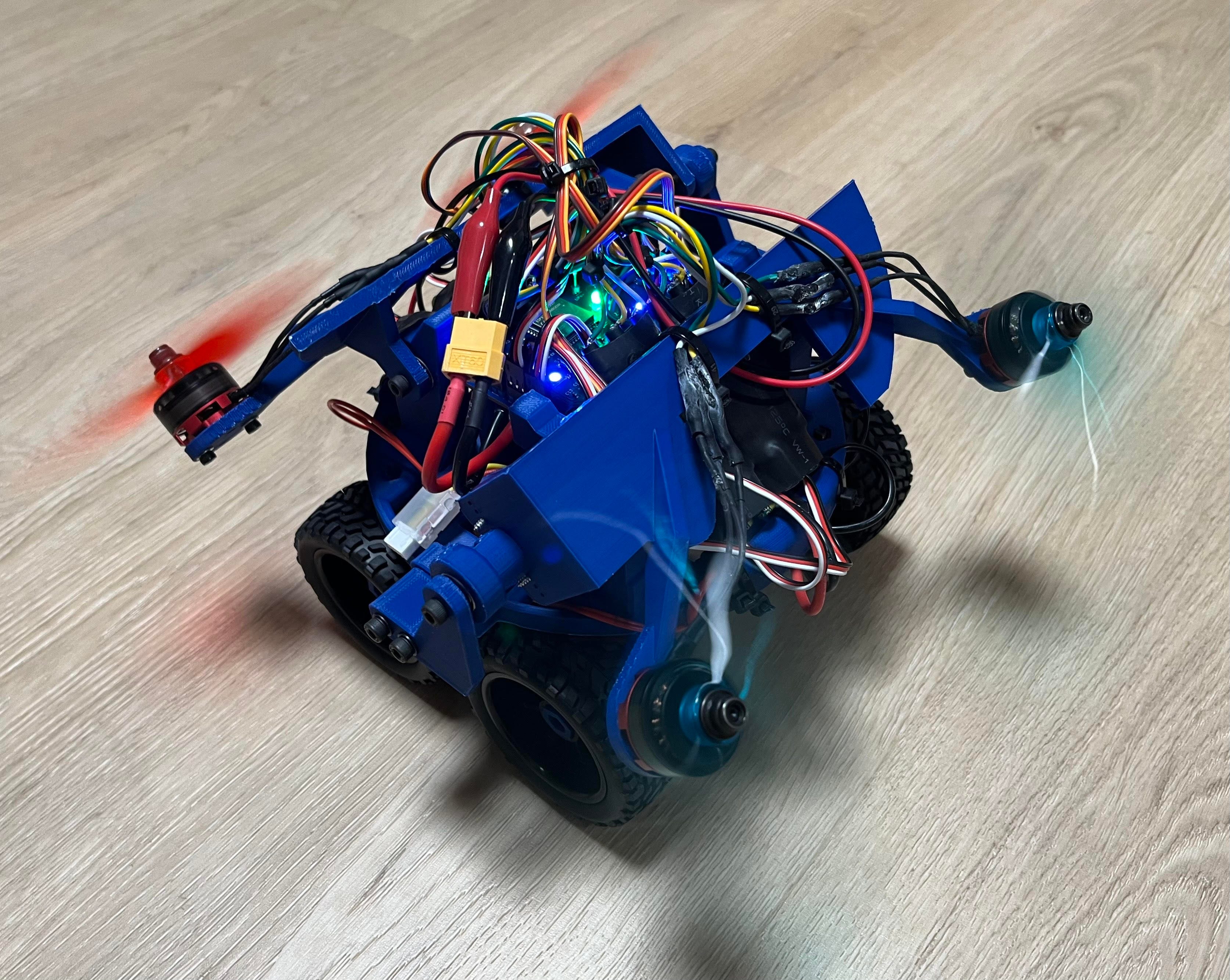
It actually has pretty good control too! Check out how it reacts to the joystick as I move it around:
Step 3:
Unfortunately, here’s what happens if I try to lift off without proper flight control software.
Step 4:
As you can see, it’s super unstable! If you’re thinking, “Oh, simple. It’s just biasing backward!” It’s unfortunately not so simple. As far as the programming is concerned they are all the same speed! The most likely possibility is that one of the motors is just ever so slightly slower. Upon replacing it, the same problem will occur with a different motor. This trend goes on for a while, all the way back around to the motor/ESC we originally replaced. There will always be some slight imperfections with the speed of each motor, which means live feedback and adjustments are crucial.
Working Concept
The main idea is that it uses an ESP32-S3 microcontroller at 2.4GHz to communicate wirelessly with my universal controller project, in addition to an MPU6050 gyroscope unit to provide real-time feedback on the drone’s position in space. (Necessary for when I come back and re-write the flight control software. If you just want to use it on the ground, you don’t need one at all.)

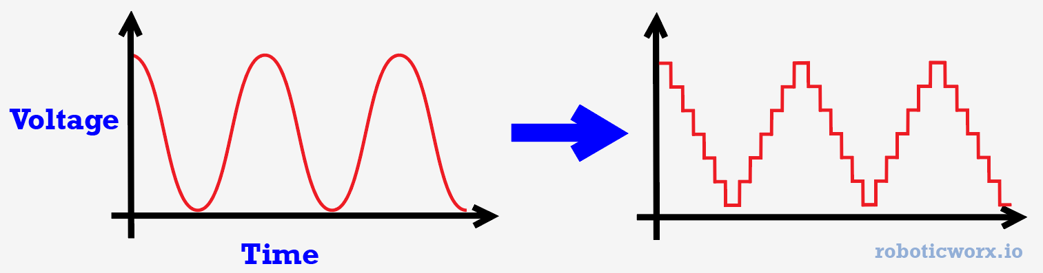
To move the BLDC motors, I’m using four ESCs (electronic speed controllers) driven by a servo motor PWM (pulse-width modulation) signal from the ESP32-S3 to communicate the speed at which I want them to rotate. This is also convenient because I can use the same servo signal for the servo motors (as it is a PWM servo motor signal).
Here’s how the different pulse lengths look:

All servos work at 50Hz, or 20ms pulse length.
The servos I chose for this project are MG996R servo motors because they’re decently powerful and are as cheap as money can buy.

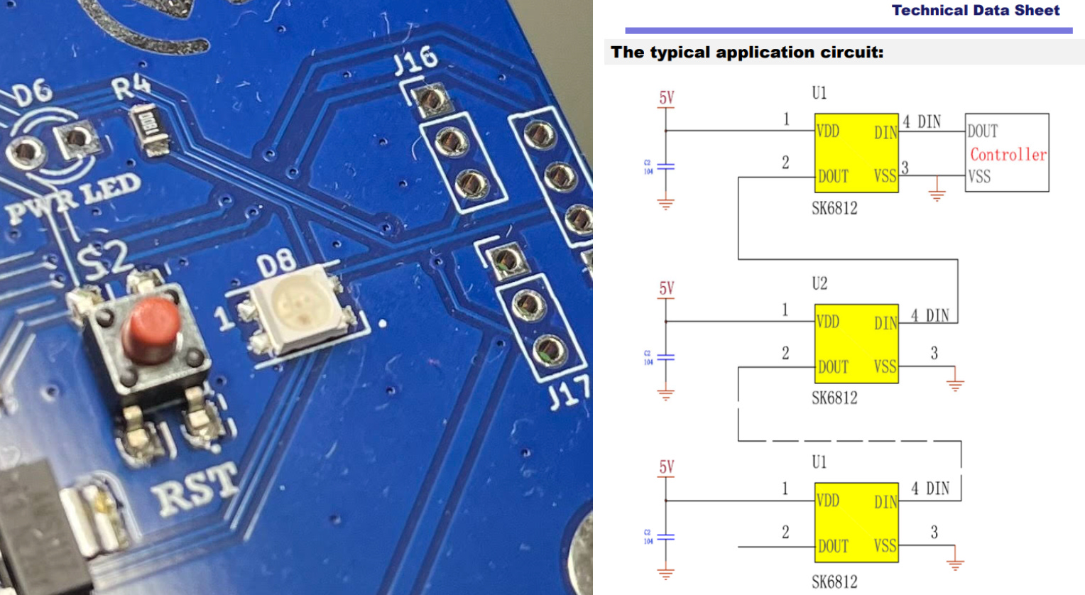
I also added some cool RGB LEDs to indicate the vehicle's state and look awesome. The ones I’m using for this project are actually super neat, as they need only one signal to vary all three of the RGB colors.
Understanding The Hardware
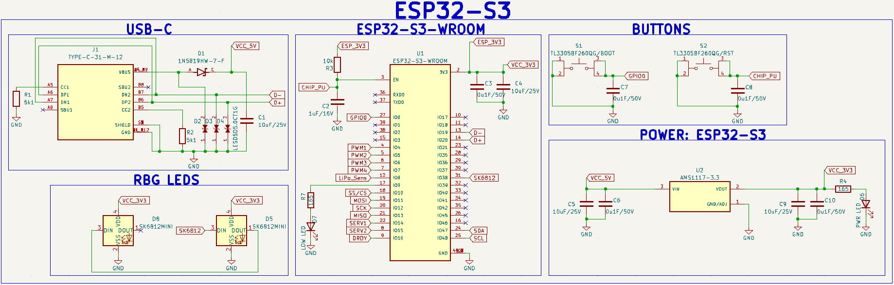
Now, let’s take a deep dive into how all the circuitry for this device works.
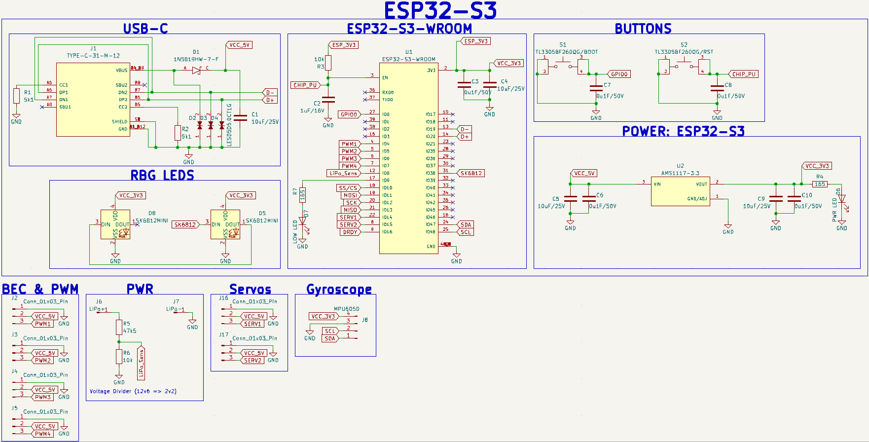
A higher-quality image can be found on my GitHub here. You may notice that on the part list, the 10uF caps are rated for 16V instead of 25V. Either works great, as we won’t be exceeding much more than 5V for this circuit. Editable board files can be found in the BOM.
The main idea for the electronics is that we need to build a circuit that can:
- Receive wireless data.
- Convert the received data into various signals.
- Send those signals to external devices (ESCs and servos).
- Communicate with the onboard gyroscope IC (integrated circuit) for live feedback whenever we set up the flight controller.
This being said a microcontroller with wireless capabilities would be perfect for the job. Of course, like all my other projects, my go-to was the ESP32-S3 or more specifically the ESP32-S3-WROOM-1 (which comes with an antenna). This is a very powerful, cheap, and straightforward microcontroller that interfaces well with the Arduino IDE. It is also the successor of the well-known ESP32.

Everything needed to build the microcontroller is in the big box labeled “ESP32-S3” on the schematic. I’ve got most of the placement values on my schematic directly from the ESP32-S3 datasheet schematic, but like my previous projects, removed some components for UART since I would only be communicating with the microcontroller via USB. I also added an extra RGB LED so they could be symmetrical on the PCB. By connecting the output of the first RGB LED (SK6812MINI) to the input of the second, you can control both of them at the same time as well which is pretty neat.
(If you’d like for them to be more radiant, you can change their footprint and replace it with the full-size SK6812 RGB LED instead of the mini version.)
If you’d like to learn more about how each component works and why I placed resistors and capacitors where I did, please feel free to check out each of them in their respective datasheets linked in the BOM (bill of materials). Sometimes, all you really need to do to learn about electronics is some good datasheet time!

With the microcontroller circuit done, all we need to do is feed all the outputs to the external components such as the ESCs, servos, MPU6050 gyro, etc.
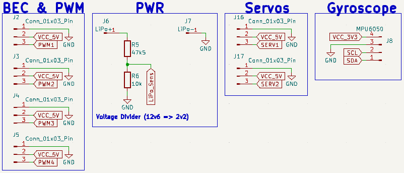
As seen above, we can use pin headers (connectors) to represent the places where we will solder/connect external components to the PCB.

Since the voltage across a battery drops as it gets lower, I added a voltage divider under “PWR” so that we could monitor the rough value of the battery’s charge. Check out my universal controller post to learn more about how we can measure voltages using ADC (analog-to-digital conversion).
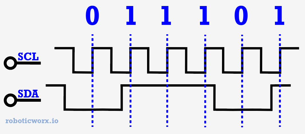
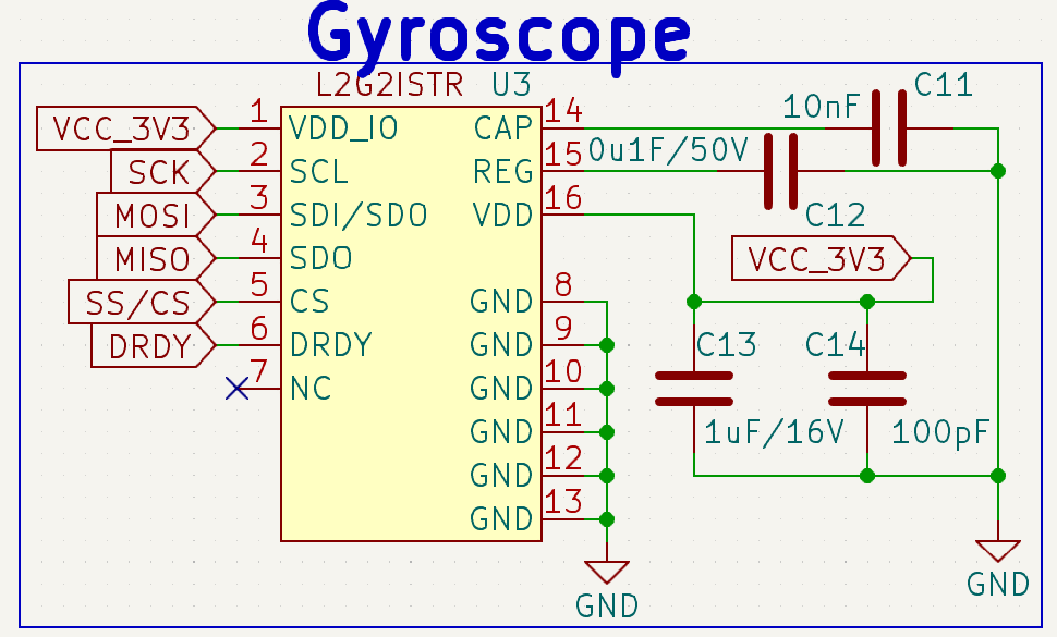
Now all that’s left is our MPU6050 gyroscope IC. We can use our microcontroller to communicate with this IC using I2C (inter-integrated circuit), which is a popular communication protocol that consists of only two wires: a clock (SCL), and a data line (SDA). It is also commonly written as IIC, as I2C in reality is i-squared-C (I^2C).
Building the Board
Confession time: I originally tried to use an L2G2ISTR gyroscope IC instead of the well-known MPU6050, as a challenge to myself to see if I could get it working. But I unfortunately couldn’t hack it.
Turns out it’s pretty hard to well-solder and troubleshoot by hand an IC that is only 2.3mm long and has all its pins on the bottom.

Even with a PCB test board, I found that when I de-soldered the component many of the pins had no solder residue on them. I tried again a few times, but when I finally got what I thought worked, I believe I may have over-soldered the IC and shorted it somewhere. Of course, there was no way to inspect it either as all the pins are on the bottom. A couple of times I was able to communicate with the IC enough to get its chip ID, but never more. It was also quite difficult to set up SPI (serial peripheral interface) communication with the chip from scratch which may have also been a contributing factor.
Anyways, eight ICs, two weeks, and $39.12+shipping later I decided to yield and just go with the well-known MPU6050 gyro haha. Let my mistakes be a lesson to you, don’t purchase super tiny ICs with pins you can’t see then try to solder them by hand!
This is also why I had to improvise my MPU6050 connections:
![]()
Luckily, when I first designed the board I broke out an I2C connection to interface with an OLED display for optional debugging so it wasn’t too bad to resolve. But don’t worry! I fixed the board you will be downloading so that you can just plug and play the MPU6050. Lucky you!

That being said, I also left where I tried to interface the L2G2ISTR for any of you brave enough to try it. Not to worry, if you leave it disconnected or fail, everything will still work with the MPU6050 (as long as you didn’t accidentally short power to ground). If you want to attempt the challenge, here is the datasheet, location, and schematic: GL!

Now to get to the rest of the PCB assembly.
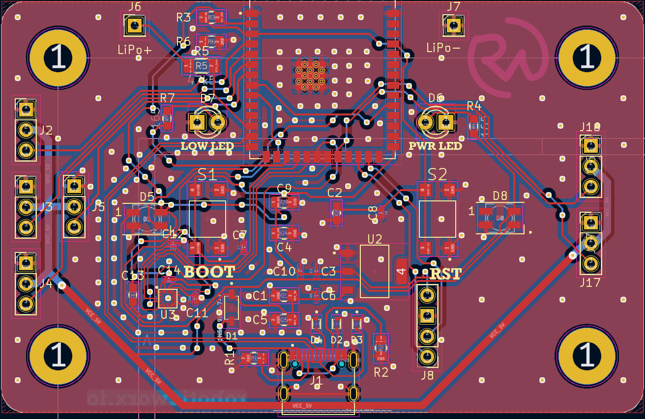
Here’s what the full PCB and routing look like:

- The Gerber/fabrication file for the board can be found here on my GitHub.
- The editable KiCad files for the board can be found here.
- The part list for all the components required in this circuit can be found here.
- I know that it can seem like a pain to have to order parts, but let me explain why it’s not! Almost all the parts I order from one project get reused, as almost everything is the exact same every time when using the same microcontroller (the almighty ESP32-S3)! (Of course, you will still have to order parts to interface with the microcontroller as needed for your project, but that’s minimal!) That being said, you only really have to order parts one time and you’ll be set for many projects to come. So, buy in bulk, and please don’t feel intimidated by them. Think about how much you’ll learn with some hands-on experience!
If you’re interested in learning more about PCB layouts and routing, check out Robert Feranec. He’s an excellent designer and I’ve learned a lot from him!
Of course, to get this board made we’re going to need to go through a PCB manufacturer. And as usual, I chose PCBWay.

Their quality is always super amazing, and they even have a KiCad plug-in so I can check out without even leaving my design software.
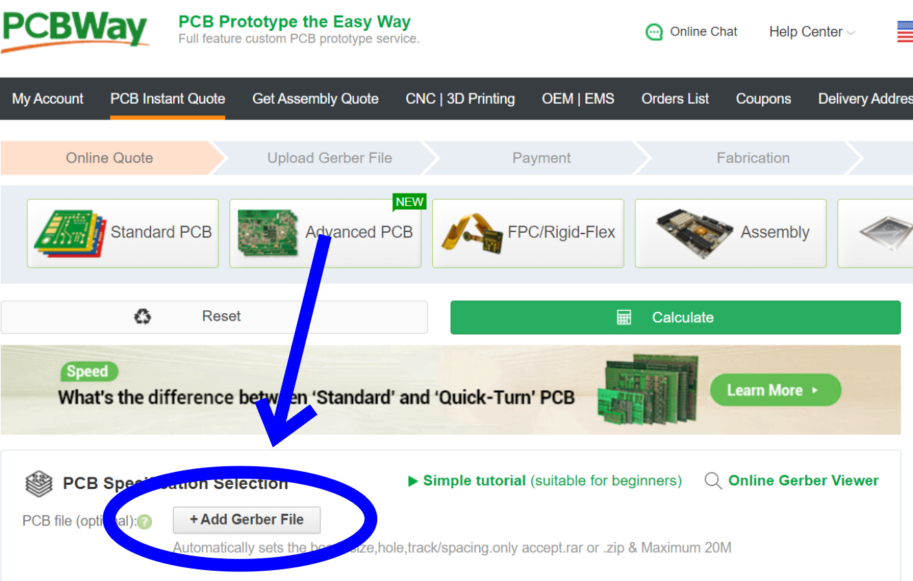
However, you can always just check out through their website by going to PCBWay.com, clicking on quick-order PCB, and uploading the Gerber/Fab file for the board. Or alternatively, just go here which I have saved in my favorites bar.
Once the boards arrived just a few days later, they looked as beautiful as always.

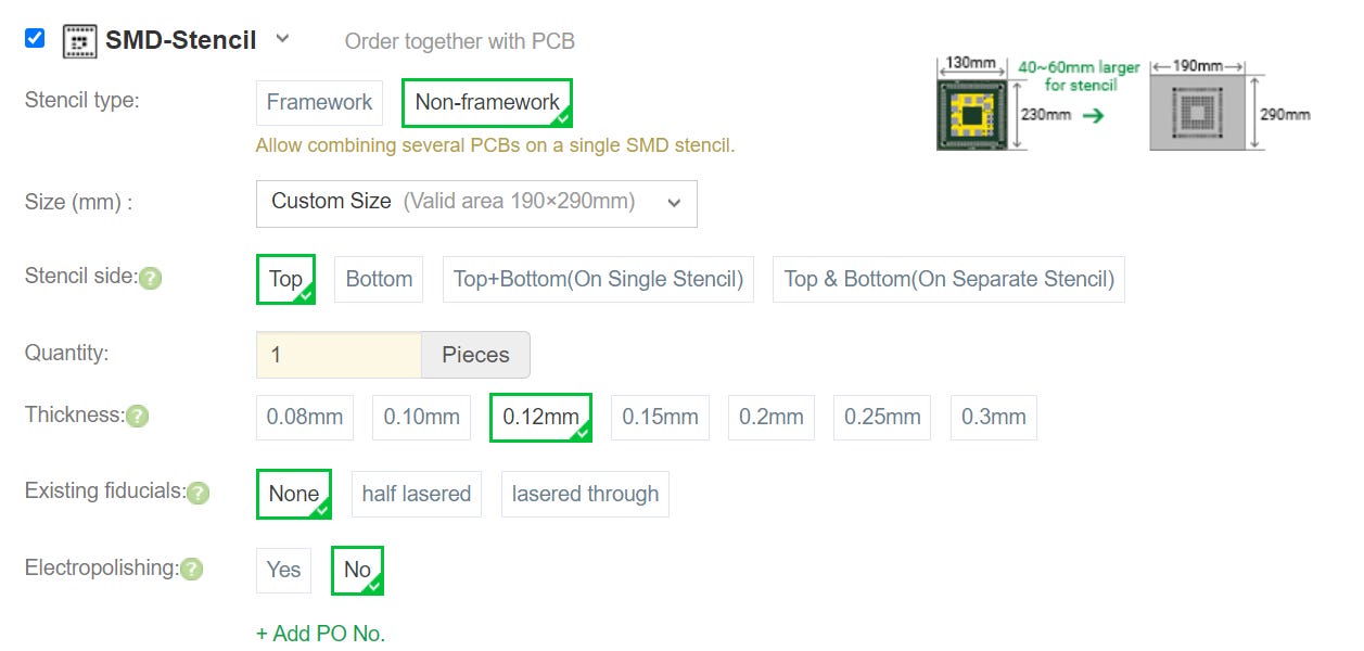
Now it’s board assembly time. I recommend purchasing a Stencil at PCB checkout to make this step wayyy easier.
The reference/placement sheet for the PCB components can be found here.
Here’s a short video outlining the assembly process:
Step 5:
Nothing quite like the smell of a freshly baked PCB.

Yours will have breakout pins for the MPU6050 and none for the OLED.
NOTE: Before uploading any code, you must put the board into bootloader mode. You can do this by holding the boot button > hitting the reset button (RST) while it’s held > and then releasing the boot button.
You may have noticed the substantial increase in my PCB assembly video quality. That would be thanks to the kind folks at LinkMicro! I just received the new LM249MS digital microscope from them and it’s been incredible! I feel like I can really see what I’m doing now when assembling the PCB, and I’m sure you feel you can finally see what I’m doing too haha.

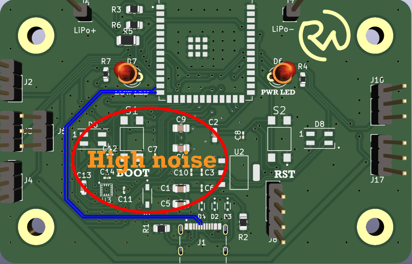
Something else interesting about this PCB layout is the USB D+/D- trace routing. I thought this would be good to touch up on, as I’ve made some mistakes with them in the past. These data lines are very important, as they carry all of the information that we use to program our microcontroller from the computer to the ESP32-S3 SoC (system on a chip). When routing these tracks, it’s important to route them as a differential pair. Meaning they need to be side-by-side with each other, as the electromagnetic fields generated by the different signals they carry cancel each other out, so as not to disturb other nearby components/adjacent traces. Here’s a great video if you want to learn more about the USB protocol.
Step 6:
However, something else important to do when routing the D+/D- traces is to try to keep them as electrically isolated from other analog signals as possible. The blue traces in this photo are the USB data lines, as you can see they are routed away from the noise areas of the PCB to keep the data as pure as possible.
Assembly
Even though this project isn’t fully completed, I still wanted to add an assembly portion for anyone who wants to make it. Nonetheless, it’s still pretty awesome to drive around and mess with! Certainly not your average RC car, quite an eye turner haha. Feel free to try to get the flight controller portion working too! I’d love to hear from you if you’re able to figure something out.
Don’t feel like scrolling forever to get past the assembly section? Skip it by clicking here!
First, you’ll want to print out all the parts. The files for those can be found here on my Thingiverse.
(Note: A lot of the parts such as the flaps, tire extenders, etc., are the same so you’ll need to print out multiple.)
The next thing you’ll need to do is grab the base piece and fill in all the hexagons engraved into the print with M4 nuts. There are quite a few. You can also go ahead and press in the two support bearings on the sides.
Note: All the exact parts and links for them can be found in the BOM.

Then, grab your tire extenders and press fit in the bearings. You’ll also need some M4x14 bolts.

After that, you can screw them into the bottom of the base.

Then, grab two MG996R servos and pop them into their mounting pads. You’ll want to go ahead and screw them in as well. The bolt for this one can be an M4x14 or longer.


Next, grab your two flaps and mount the servo horn. You can use a long M3 bolt as a guide in the middle to help keep it from slipping while you screw it in.

With that done, press a bearing into its place on the flap and snap it onto the end of the servo horn. It’s okay if it flexes a little while you do this.
Note: I recommend calibrating the servo by powering it on and moving it to the upward position electronically prior to mounting it. Wouldn’t want the restrictive 180-degree motion to be directed the other way!

After that, you can go ahead and screw in the other side with an M4x20 bolt for added support.

Revisiting the other side, you’ll want to add on the bearing support piece to keep too much force from damaging the servo while the propellers are on. You can use another M4x20 bolt for this.

Just be sure that there’s an M4 nut inserted into the propeller flap piece, otherwise, the bolt that goes into the bearing won’t be able to thread.

After that, it’s time to start working on the wiring. I recommend going ahead and mounting the propellers on all the BLDCs (just sinch the nut down tight on the propeller).

Then, screw all of the BLDCs onto the flaps using some M3x10 bolts.

In doing so, I’d test each one individually with the ESC to ensure they are spinning in the direction. If they’re not, you can change the polarity by switching either of the outside wires with the middle one. You can connect them with the motors by directly connecting them from the three poles of the ESC to the three poles of the motor. I’d do these tests with removable alligator clips first, then write down the configuration for each.

Once you’re confident in how to connect each so that they spin correctly, you can make it more permanent with some solder. I recommend each wire be around 140mm so that they can flex comfortably as the servo motors move. I know it’s not the ideal way to connect them, but it’s the price we pay for cheap ESCs. Plus, these wires aren’t going anywhere.

You can ignore the PCB in the background, that’s the next step.
Now, we can go ahead a put in our LiPo battery and then mount the PCB over it. There are no metal threads for the PCB, so I recommend using long bolts such as M3x30s for increased area and not sinching them too tight. Don’t want it to strip the plastic!

While we’re at it, we can go ahead and plug in our ESC wires. It doesn’t really matter which one goes where, but I recommend creating a numbering system. I did it such as below, then plugging one into the one labeled J2, two into J3, three into J4, etc. It makes visualization easier.


As far as the servos, it really doesn’t matter. They move in sync! (Just make sure not to accidentally short them by connecting power to the ground pin of the servo!)
Next, we break out magnificent creation that is zip-ties and just go to town. lol.


You can secure the ESCs in a similar way.

I hold off on securing the ones that block the USB port until after you upload the code though!
As far as routing power goes, I recommend getting some thick wire and soldering both terminals to it.

I used two smaller wires since I didn’t have any thicker ones. (Ignore the wheels for now.)
After that, you should route each of them to their terminals on the other side and solder them on. You can thread them in and out of the base to make them more secure.

(Wheels are the next step.)
Now you’re just about done!
To attach the wheels, grab your 3D-printed wheel snags and press them into the hexagons on the outward sides of the wheels. Then, press some M4 nuts into them.

With that, using some spacers, slide an M4x30 bolt through the bearing and out the spacer on the other end.
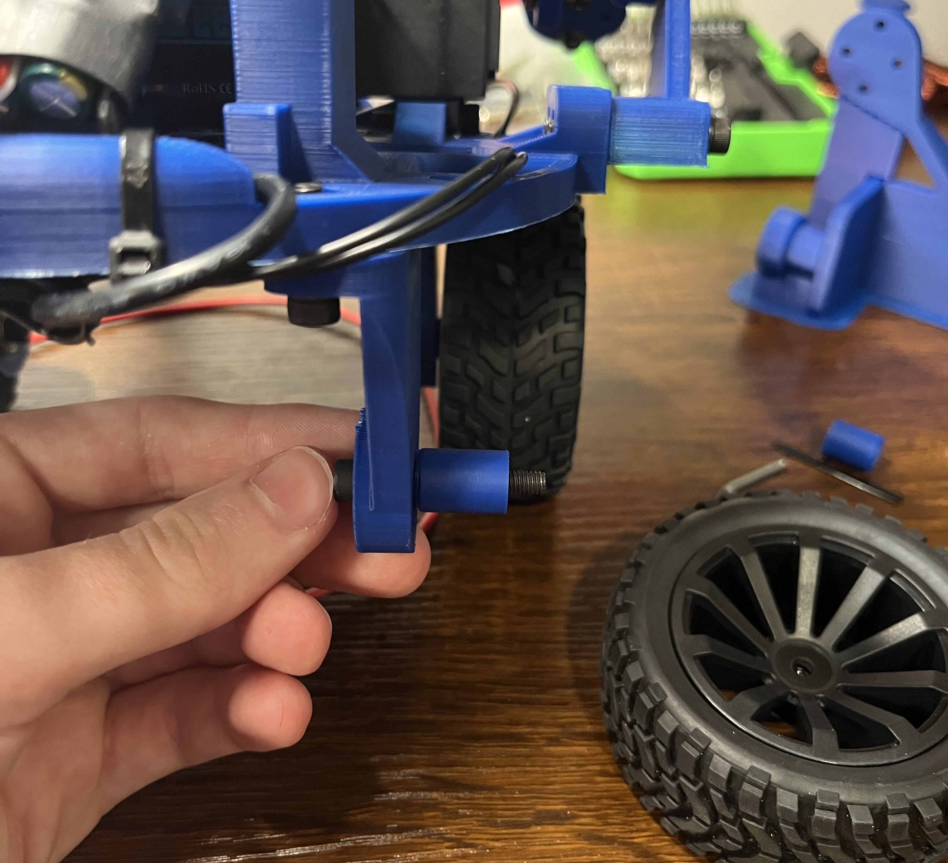
Then just screw on the wheels.
You may have to do some more zip-tieing afterward to make sure all the wires aren’t tangled as well as not in the way of any of the propellers.
That’s all! Thanks for staying with me.

Programming
The programming for this project isn’t too bad (since there’s no flight controller software yet). Here’s a run-down of how it works: basically we just have to control six servo motors individually (ESCs and servos use the same signal) based on data we receive from the universal controller. Let’s dive in.
The full project code can be found on my GitHub here.
These are the libraries you will need installed for this project:
#include "ESP32_New_ISR_Servo.h"
#include <WiFi.h>
#include <esp_now.h>
#include "ESP32_New_ISR_Servo.h"
#include <FastLED.h>
#include <Adafruit_MPU6050.h>
#include <Adafruit_Sensor.h>
#include <Wire.h>
I am using the ESP32_New_ISR_Servo library because the standard ESP32Servo doesn’t work the same way on the ESP32-S3.
First, we define some pins and the on-time in microseconds for the servo signal. (Normally 1000-2000μs, but we can adjust them higher or lower if the servo still can’t move a full 180 degrees.)
#define MIN_MICROS 1000
#define MAX_MICROS 2000

const int I2C_SDA = 47;
const int I2C_SCL = 48;
const int LED_PIN = 38;
const int NUM_LEDS = 2;
const int LOW_LED = 9;
We can assign a servoIndex to determine the individual state of each servo motor.
int servoIndex1 = -1;
int servoIndex2 = -1;
int servoIndex3 = -1;
int servoIndex4 = -1;
int servoIndex5 = -1;
int servoIndex6 = -1;
For the rest of the variables, we can just assign their datatype and set them to zero.
To receive the data from the controller, we need to define a data structure to hold it. We can use a callback later to copy the information from memory. You can more about ESP-NOW (the protocol we’re using for wireless) here.
typedef struct struct_message {
  int a; // Pot1
  int b; // Pot2
  int c; // J1X
  int d; // J1Y
  int e; // J2X
  int f; // J2Y
  int g; // Button number
} struct_message;

struct_message dataRecieved;

esp_now_register_recv_cb(callData);
We can then add the RGB LEDs through some functions with the FastLED library and set their brightness. Since it’s meant for full-size SK6812 LEDs, I lowered the brightness to 60 of 255 to make sure they don’t burn out.
FastLED.addLeds<SK6812, LED_PIN, GRB>(leds, NUM_LEDS);
FastLED.setBrightness(60);
Then, a while loop can be used to stop the program if the MPU6050 isn’t responding. If it is, we can set the default values.
  if (!mpu.begin()) // Initialize MPU6050
  {
    while (1)
    {
      fill_solid(leds, NUM_LEDS, CHSV(0, 255, 255));
      FastLED.show();
      delay(20);
    }
  }

  mpu.setAccelerometerRange(MPU6050_RANGE_8_G);
  mpu.setGyroRange(MPU6050_RANGE_500_DEG);
  mpu.setFilterBandwidth(MPU6050_BAND_5_HZ);
To attach the servos to their respective pins, we can use the setupServo() function. It is also necessary to allocate a timer for the ESP32-S3 to use for the PWM signals.
  ESP32_ISR_Servos.useTimer(USE_ESP32_TIMER_NO);
  servoIndex1 = ESP32_ISR_Servos.setupServo(4, MIN_MICROS, MAX_MICROS);
  servoIndex2 = ESP32_ISR_Servos.setupServo(5, MIN_MICROS, MAX_MICROS);
  servoIndex3 = ESP32_ISR_Servos.setupServo(6, MIN_MICROS, MAX_MICROS);
  servoIndex4 = ESP32_ISR_Servos.setupServo(7, MIN_MICROS, MAX_MICROS);
  servoIndex5 = ESP32_ISR_Servos.setupServo(14, 544, 2450);
  servoIndex6 = ESP32_ISR_Servos.setupServo(15, 544, 2450);
Since BLDC motors typically have a safety function that requires them to be off during startup, we have to set their speeds to zero and wait a few seconds until they are ready. I set the servos to 120 just since that’s a relaxed position for them where they aren’t moving into anything.
Important note:Your servo motors likely won’t be in the exact same starting position as mine. This means you will have to adjust the values sent to the servo motors (index 5 & 6) to the ones that work for you. Otherwise, they may try to move somewhere they physically can not move to and break something.
  ESP32_ISR_Servos.setPosition(servoIndex1, 0);
  ESP32_ISR_Servos.setPosition(servoIndex2, 0);
  ESP32_ISR_Servos.setPosition(servoIndex3, 0);
  ESP32_ISR_Servos.setPosition(servoIndex4, 0);
  ESP32_ISR_Servos.setPosition(servoIndex5, 120);
  ESP32_ISR_Servos.setPosition(servoIndex6, 120);
  delay(3000);
In the super loop, we can get the data from the MPU6050 and use a blink-without-delay concept to only update the colors every 20ms. This makes for a smooth color transition.
  unsigned long currentMillis = millis();

  sensors_event_t a, g, temp;
  mpu.getEvent(&a, &g, &temp);

  if (currentMillis - previousMillis >= interval)
  {
    previousMillis = currentMillis;
    static int i = 0;
    fill_solid(leds, NUM_LEDS, CHSV(i, 255, 255));
    i++;
    if (i >= 256)
      i = 0;
  }
  FastLED.show();
Now we begin the button chain. This just consists of a long if-else chain that does different things based on the different buttons we press on the controller. These can be configured for anything you’d like! These are just what I chose.
To make things less long, I’ll only do one example. If dataRecieved.g (aka, one of the buttons are pressed) is that of the button on pin 35, set the speed of all the propellers to that of dataRecieved.a (aka, the top-left potentiometer) which goes from 0-180.
if (dataRecieved.g == 35) // Normal control
  {
    prop1 = dataRecieved.a;
    prop2 = dataRecieved.a;
    prop3 = dataRecieved.a;
    prop4 = dataRecieved.a;
  }
You can do something similar with the joysticks.
If dataRecieved.e (aka, the right joystick’s x-axis) is a 1 (on), set the speed of all the right propellers to that of dataRecieved.a (aka, the top-left potentiometer again). I chose only the right propellers because that would mean their forces would cancel and result in a right turn.
  if (dataRecieved.e == 1) // J2X
  {
    prop4 = dataRecieved.a;
    prop2 = dataRecieved.a;
  }
This goes on for a while.
After that, we can use the constrain() function to make sure none of the data values we write to the propellers exceed their maximum value of 180 degrees, or 2000μs on time. This isn’t super necessary, but still a good safety precaution just in case you send the wrong controller value, etc.
  prop1 = constrain(prop1, 0, 180);
  prop2 = constrain(prop2, 0, 180);
  prop3 = constrain(prop3, 0, 180);
  prop4 = constrain(prop4, 0, 180);
Then, we can just send the propeller values to the pins attached to the BLDCs as a PWM using the setPosition() function.
  ESP32_ISR_Servos.setPosition(servoIndex1, prop1);
  ESP32_ISR_Servos.setPosition(servoIndex2, prop2);
  ESP32_ISR_Servos.setPosition(servoIndex3, prop3);
  ESP32_ISR_Servos.setPosition(servoIndex4, prop4);
That’s it! Again, if you’d like to explore the full code, you can check it out here!
NOTE: Before uploading any code on a custom ESP32-S3, you must first put the board into bootloader mode. Otherwise, you’re computer will not be able to properly recognize the device. You can do this by holding the boot button > hitting the reset button (RST) while it’s held > and then releasing the boot button.
BOM
This is the Bill of Materials for my Hovercar project.
I’ll put everything that you need to have here so that you don’t have to go scrolling around looking for the links I sprinkled throughout the article.
- All the CAD can be found here. I’ve attached a STEP file for editing if you’d like to make any changes. In addition, I attached a SolidWorks file for each in case that’s easier.
- All the part numbers and quantities for the SMD (surface-mounted device) components on the PCB can be found here through this link. Note: They don’t have to be the exact same components so long as they have the same function and fit on the footprint. (Feel free to edit the board files if you want to use something else though!)
- The PCB placement sheet can be found here.
- Four-pack of ESCs (electronic speed controllers).
- Four-pack of BLDCs (brushless DC motors).
- Pack of MG996R servos.
- RC car wheels.
- Small drone bearings.
- Pack of propellers.
- Small 3S 1300mAh LiPo.
- MPU6050 module (only if you want to attempt flight).
- ESP32-S3 DevKit (if you want to skip the custom PCB)
- 3V3 LEDs.
- Pin headers.
- Pack of holy zip-ties.
- Optional (if you don’t already have them):
- Some nuts & bolts.
- Basic screwdriver kit (one of many options).
- Some hook-up wire.
Disclosure: These are affiliate links. I get a portion of product sales at no extra cost to you.

Thanks so much for reading! I hope this was a helpful and informative article. If you decide to do the build, please feel free to leave any questions in the comments below. If not, I hope you were still able to enjoy reading and learn something new!
Have constructive criticism? I’m always looking to improve my work. Leave it in the comments! Until next time.
Be sure to follow me on Instagramand check out these projects on my homepage! :)


![Tim's Mechanical Spider Leg [LU9685-20CU]](https://content.instructables.com/FFB/5R4I/LVKZ6G6R/FFB5R4ILVKZ6G6R.png?auto=webp&crop=1.2%3A1&frame=1&width=306)


