

Introduction: CNC3018 Pro - Full Metal Upgrade


As a student of ČVUT University in Prague navigating the world of making, I often found myself limited by the capabilities of my CNC3018 Pro. The promise of milling aluminum seemed elusive with the stock setup, prompting me to seek ways to enhance its functionality. The prize money earned from my successful Nerdy Gurdy project on Instructables became the catalyst for this upgrade.
In this instructable, I'll take you along my journey as I share the process of upgrading the CNC3018 Pro. The objective is to transform it into a sturdy tool capable of precise and efficient aluminum milling. The experiences gained from my previous projects, coupled with the invaluable knowledge shared by the maker community, have empowered me to push the boundaries of what my CNC3018 can achieve. Join me in this exploration of enhancements and modifications that will bring new capabilities to your CNC3018, unlocking the potential for a broader range of machining endeavors.
Supplies

Machine Parts:
- CNC3018 machine (existing or to be purchased as a kit)
- Linear guides (MGN12H) and corresponding rails
- Ballscrew SFU1605 for X and Y axes
- NEMA17 stepper motors
- Planetary gearboxes (1:3 ratio) compatible with NEMA17 motors
- 4040 aluminum extrusions
- 200mm 20100 aluminum extrusion
- 4x 360mm 2020 aluminum extrusions
- Shoulder bolts
- T-nuts and screws
- Z-axis adaptor plate
- Aluminum Router clamp mount
- Woodworking Electric Trimmer 1/4"
- Metal strip (shim for the router)
- CNC cut parts
- Steel front and back plates
- Reduction plates (for mounting linear guides and ball screws)
Electronic Components:
- Makerbase MKS TinyBee controller board
- A4988 stepper motor drivers
- FluidNC CNC firmware
- Stepper cables
Additional Supplies:
- Various screws and bolts
- Cordless drill
- Tapping tools
- Various tools for assembly (screwdrivers, wrenches, etc.)
- Safety equipment (gloves, safety glasses)
Optional:
- Paint and materials for aesthetic enhancements
Note: Specific quantities and sizes of components may vary based on your CNC3018 model and personal preferences. Adjustments might be needed based on any additional modifications or improvements you decide to implement during the project.
Step 1: Front Plate Upgrade


A front plate upgrade involved a complete overhaul of the plastic front and back plate. Recognizing the limitations of the stock linear bearing with rods, I opted for a substantial upgrade to MGN12H linear rails.
The redesigned front plate was made in Fusion 360. I incorporated crew mounting holes for 20x40 aluminum extrusions instead of the ones for linear rods. These extrusions provided a sturdier foundation and it allowed the MGN12H linear rails to be securely fastened, onto extrusions. Furthermore, the front plate serves the additional function of a stop for the linear rails, preventing unintended dislocation. The mentioned 20x40 extrusions were a little longer than in the original CNC 3018, so the machine has a longer reach, 360mm to be exact.
To bring my design into tangible reality, an order from a local CNC laser-cutting company was needed so the original plastic part could be replaced with a steel (S355) one I designed.
Attachments

Step 2: Fastening


The next crucial step centered around the meticulous process of fastening. The integration of MGN12H linear rails necessitated a purchase of more m3 tnuts. Additionally, 3D-printed parts were crafted to assist in aligning the rails precisely to the center of the 2020 extrusions, ensuring an accurate and stable assembly.
Each 20x40 aluminum extrusion was carefully tapped to accommodate screws. Tapping into the 20x40 aluminum extrusions became a meticulous process, where the use of a cordless drill played a pivotal role in initiating the tapping at the correct angle. Subsequently, a switch to manual tapping ensured precision, aligning with the meticulous standards set for this upgrade.
Taking the commitment to robustness a step further, collaboration with the same local CNC laser-cutting company that crafted the front and back plates yielded an upgraded set of side plates. Replacing all plastic structural components with steel counterparts brought a unified combination of strength and precision to the entire assembly.
This extensive upgrade, merging precision and durability, establishes the foundation for the CNC3018's enhanced capabilities, paving the way for more intricate machining endeavors.
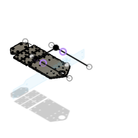
Step 3: Ballscrews


The subsequent stage involves substituting the acme threaded rods with ball screws SFU1605, as the ball screws offer a notable improvement over acme threads in CNC applications, primarily due to their superior precision and reduced friction. The rolling motion of ball bearings along the helical groove of the ball screw results in smoother and more efficient movement compared to the sliding motion of acme threads.
During the design of the front and back plates, careful consideration was given to ensure compatibility with BF12 and BK12 ball-bearing housings. Additionally, a significant upgrade was made to the ball bearings themselves. The original bearings were replaced with angular bearings 7001AC which are more suitable for this particular application.
However, it's important to note that the original screw holes on these housings were slightly undersized for European metric screws. To ensure compatibility and a secure fit, I carefully enlarged the screw holes through drilling, ensuring that the components were seamlessly integrated into the CNC3018 upgrade.
Step 4: Mounting Bed to the Rails and Screw


The CNC3018 is a bedslinger type CNC machine, characterized by its configuration, where the workpiece moves along the X-axis and the cutting tool moves along the Y-axis. This design is distinct from gantry-style CNC machines, where the cutting tool moves along both the X and Y axes while the workpiece remains stationary. The CNC3018's original bed piece will serve as a fundamental component in the X-axis movement.
However, as I embarked on the upgrade journey, it became evident that both the ball screw nut housing and the MGN12H linear rails were not directly compatible with the stock bed. To overcome this challenge, I leveraged Fusion 360 to design precision reduction plates made from aluminum.
The process of making these reductions was surprisingly straightforward, since I designed the front and back plates in a way, that rails and ballscrew nut housing end up on the same virtual plane (the same height). Thanks to this, the reduction plate's thickness was not crucial, as long as they all had the same thickness.
Due to the carefully designed reduction plates, the mounting hardware from the original machine could be reused.
Step 5: Power for the X-axis


In this build, I decided to keep the original NEMA17 stepper motors, partly due to budget constraints. To augment the power of these motors on the X and Y axes, I bought NEMA17-compatible planetary gearboxes with a 1:3 ratio. This enhancement delivered better torque, but on the other hand required an additional reduction from the planetary gearbox, which has a different diameter shaft, to the shaft of the ballscrew. Some kind of reduction would be needed anyway, thanks to the ballscrew upgrade.
Another advantage of keeping the NEMA17 motors is the wide variety of affordable electronics designed for 3D printers, offering cost-effective options for driving the motors. As a part of this upgrade, I had to shorten the stepper motor shaft to fit into the gearbox.
Step 6: Y Axis Construction


For the Y-axis, much of the construction process mirrored that of the X-axis, with a notable exception: the original Y-axis carriage components were deemed inadequate due to their plastic construction, but the stock 2020 extrusions were used.
I opted for a sturdier solution of the carriage, that is easy to work with. I incorporated a 20100 aluminum extrusion along with additional aluminum mounting plates. This modification not only enhanced the Y-axis strength and durability but also ensured a more robust and reliable performance for the CNC3018 overall.
Step 7: Y Carriage


In the creation of the CNC carriage and Z-axis, I utilized a 20100 aluminum extrusion plate as the foundation for the Z-axis, mounting it onto the MGN12H rails. Unlike previous steps, where additional mounting plates were required, this time, I devised a new method to attach the 20100 directly to the rails. To accommodate the mounting of the Z-axis MGN rails, one side of the 20100 extrusion needed to remain unaltered, prompting the utilization of the unique T-nut and screw mechanism. Due to the challenge of precision drilling through the 20100 plate, I explored an alternative approach. Oversized M4 T-nuts were secured to the rail carriages using M3 screws, subsequently, I drilled holes into the extrusion plate, strategically placed to allow tightening of the aforementioned M3 screws. This arrangement effectively clamped the T-nuts onto the extrusion plate, providing a secure and stable connection.
But before mounting I proceeded to tap the holes in the 20100 extrusion. Surprisingly, tapping the Chinese extrusion was easier than expected, while the locally sourced 2040 proved to be more challenging, suggesting potential variations in quality. The bottom plate, cut on cnc router with the reductions was then introduced, transforming the entire carriage into a reversed L shape. Behind the lower MGN rail, an additional rail was incorporated to lend support to the Y axis. This design choice was implemented to counteract twisting forces on the Y-axis rails effectively. Furthermore, the plate featured strategically positioned mounting holes for securing the bearings of the Z-axis ballscrew.
For the next step, I mounted another 2020 extrusion on top of the 20100 extrusion, securing it with screws. On the upper side of this, I attached a generic Nema 17 mounting plate to facilitate the mounting of the Z-axis stepper motor.
Step 8: Z Axis

In the Z-axis assembly, I acquired a Prusa NEMA 17 motor with a ballscrew as a shaft, sourced from a Prusa SLA printer that had malfunctioned. The user opted to sell the salvaged parts online. To integrate this motor into the CNC3018, an offset part was needed since the MGN rails were positioned relatively far behind the screw. For this purpose, I employed 4040 extrusions, featuring holes exactly 20mm apart, matching the spacing of the MGN rail carriages. To secure them, I utilized shoulder bolts with a 3mm thread (matching the carriage) and a smooth part diameter of 5mm (fitting the extrusion holes). These shoulder bolts were instrumental in attaching the Z-axis adaptor plate to the rails, utilizing the 4040 extrusions as the necessary offset.
Step 9: Router


For the spindle component of the CNC3018 upgrade, I explored various spindle options available online. After evaluating the reviews, it became apparent that many commercially available spindle upgrades, made specifically for CNC 3018 pro, were both expensive and lacked satisfactory performance. As an alternative, I opted for a cheap "Woodworking Electric Trimmer 1/4" (bought for $20 inc. shipping) along with an aluminum clamp mount intended for use with the router. However, upon testing, the router proved to be too small for the clamp, even when tightened to the maximum extent. To address this issue, I implemented a quick and pragmatic solution by adding a metal strip as a shim to the clamp. Fun fact, the shim was a can of beans, which has almost the right size and shape (and yes, I cut myself). While this served as a temporary fix, it remains a candidate for future improvements in the ongoing refinement of the CNC3018.
This choice of the "Woodworking Electric Trimmer 1/4" and an aluminum clamp mount was deemed the most cost-effective option with acceptable performance at the time of the upgrade. Looking ahead, future considerations may include exploring alternatives such as a Chinese air-cooled spindle with a 2.2kW rating, like this one, for potentially enhanced performance and reliability. I might even try to mill some softer steels with this future spindle upgrade.
Step 10: Electronics


For my controller board, I went with the Makerbase MKS TinyBee, a board equipped with the ESP32, allowing for wireless control through WiFi. What caught my interest was its compatibility with CNC applications. I chose FluidNC as the firmware, and the installation process via the web interface was smooth. With the capability to control up to 5 axes, this board leaves room for potential upgrades like a tool changer that I have in mind. For stepper drivers, I decided to reuse the A4988 stepper drivers from the original CNC3018 board.
Another upgrade to the electronics was a switching 24v 10 amp PSU, instead of the stock brick.
Step 11: Configuration: Setting Up FluidNC and Axis Calibration


Once all the mechanical upgrades are in place, it's time to configure the CNC3018 for optimal performance. I started by installing the fluidNC CNC firmware onto the Makerbase MKS TinyBee controller board. This firmware is compatible with the mentioned board and can be easily installed via a web interface. Btw. you have to connect the power supply to make the board visible, for the installation, the USB-C connector only won't suffice.
With the firmware in place, the next crucial step is to calibrate the axes, especially considering the addition of the planetary gearboxes. The gearboxes alter the overall movement and torque of the stepper motors, and accurate calibration ensures precise control and accurate machining.
I followed the specific calibration procedures outlined in the fluidNC documentation. This often involves adjusting steps per millimeter and other relevant settings for each axis.
Proper configuration and calibration are essential for achieving accurate and repeatable results in your CNC machining endeavors. So I took the time to fine-tune these settings.
Step 12: Finish

Yet, this is not just an end; it's a gateway to future possibilities. The CNC3018 now stands as a versatile tool, with plans for a tool changer and a vibrant paint job on the horizon and maybe even some epoxy granite between the extrusions of the X-axis. Thanks for reading this, and being part of this journey.
Stay tuned for a YouTube video showcasing my new CNC3018's capabilities and the entire upgrade process. Until the next project, happy making!
Kudlas

Participated in the
CNC Student Design Challenge


