

Introduction: ChromaDome - a HemiSpherical Decorative Lamp


This project is about building a hemispherical LED lamp that can be used as a decorative piece or for ambient lighting. The LEDs are arranged in a pattern to create a visually appealing effect. The semi-transparent shell diffuses the light, creating a soft and relaxing glow.
The goal of this project is to create a beautiful and unique lamp that can add a touch of personality to any space. The lamp is not intended for reading or task lighting, but rather for creating a mood or ambiance.
The components of the lamp are 3D printed, including the base, the LED support and the semi-transparent hemisphere. This allows you to customize the design of the lamp to your liking.
The LEDs are controlled by an Arduino Nano module, which can be programmed to create different lighting effects.
This project is a great way to learn about LED lighting, 3D printing, and Arduino programming. It is also a fun and creative project that can be enjoyed by people of all skill levels.
Here are some of the benefits of using this desk lamp:
- Beautiful and unique design: The hemispherical shape and semi-transparent shell create a visually appealing look.
- Soft and relaxing light: The diffused light creates a calming and relaxing atmosphere.
- Customizable: The 3D printed components allow you to customize the design of the lamp to your liking.
- Arduino controlled: The Arduino Nano module allows you to program the lamp to create different lighting effects.
Here are some additional details about the project:
- The LEDs used in this project are WS2812B addressable LEDs. These LEDs allow you to control the color and brightness of each individual LED.
- The Arduino Nano module is used to control the LEDs. The Arduino Nano is a small and affordable microcontroller that is easy to program.
- The lamp is powered by a 5V power supply. The power supply can be a USB power adapter or a wall adapter.
- The lamp can be programmed to create different lighting effects. Some examples of lighting effects include:
- Solid color: The lamp can be programmed to display a solid color.
- Color changing: The lamp can be programmed to change colors through a spectrum.
- Fading: The lamp can be programmed to fade in and out of different colors.
- Blinking: The lamp can be programmed to blink different colors.
However, I wanted to try something else, so I created two other small programs for this lamp. One program generates color palettes based on the golden ratio that fade into each other. The other program uses many predefined color palettes that fade into each other, similar to the first program. More details are available in the "Software" step.
Of course you can use a Wemos D1 Mini as a microcontroller with WLED installed for many many other effects.
The possibilities are endless! With a little creativity, you can program the lamp to display any lighting effect you can imagine.
Step 1: Materials, Components, Software Needed


Also we need things...
- Some black (or other color) PLA
- Some transparent or white PLA or PETG
- WS2812 LED strip - 100 Leds/m
- Arduino Nano module
- 5V/2A power supply with on/off switch
- Different color wires
- Hot Glue
You can find the STL file for 3D printing on Tinkercad here,
there are also attached below. As you ca see there are 2 led modules support variants and 2 semitransparent shell variants.


Step 2: Methods for Uniformly Distributing Points on a Sphere's Surface
Distributing points evenly on a sphere is crucial in fields like physics, graphics, and geometry. This challenge arises from the sphere's non-Euclidean nature. I explored several existing methods to find the best fit for this project.
- Uniform Disk Sampling: This simple method distributes points on a flat disc and projects them onto the sphere. However, it clusters points near the poles.
- Midpoint Displacement: This iterative approach generates points at midpoints of subdivided squares. It's efficient but loses uniformity with higher point density.
- Hammersley Points: These points follow a low-discrepancy sequence, ensuring good uniformity but requiring more computation for large sets.
- Fibonacci Lattice: This method, based on the golden spiral, creates points by subdividing a square with specific offsets. It achieves excellent uniformity and is relatively easy to implement.
By comparing the average distance between nearest neighbors (ADNN), research shows that the Fibonacci Lattice excels in uniformity, making it the ideal choice for this project.
Additionally, its straightforward implementation makes it a practical solution.
Step 3: Codeblocks...code
For the code I took inspiration from the article published here (there are also many other examples on the net) and implemented a simplified approach in Tinkercad's Codeblocks.
The adaptation is not too difficult. For example, in Codeblocks I am not interested in Cartesian points (x, y, z), but only polar points (latitude and longitude in code), as you can see in the picture below.

This is an example of how the code works, which places 200 points (small spheres) on the surface of a sphere with a diameter of 160. You can have fun with the code to see how it works. A few observations:
- Only a maximum of 200 primitives (small spheres) can be generated, which is a Codeblocks limitation.
- The golden ratio is phi = (1 + sqrt(5)) / 2, but I used the calculated value with three decimal places as a constant.
- Rotation around the x and y axes is interchangeable, only the generated virtual sphere rotates by 90 degrees.
- The uniform distribution, aesthetically pleasing, is along the Z-axis, making it an ideal choice for generating the LED support hemisphere.
I continued with the generation of the hemisphere on which the LEDs are mounted. I used three Codeblocks programs, two for generating holes for connecting the wires soldered to the LED modules and another for creating facettes on the generated hemisphere for the best possible bonding, on a flat surface, of the LED modules. It will be much clearer if you watch the video above.
You can find the Codeblocks programs on Tinkercad: here the demo, here the "dome_holes_1" and the "dome_holes_2" also the "dome_facettes".
Step 4: Printing, Soldering, Assembling


The parts that need to be 3D printed are on Tinkercad, the support for the LED modules and the base are made of black PLA, and the dome is made of transparent PETG.
I have to admit that I spent a lot of time experimenting with various dome designs and 3D printing options, for the best LED light diffusion.
I left both versions on Tinkercad, the difference between them being the thickness of the spherical shell, one being 2mm and the other 4mm. For printing, I tried several different materials and colors, including PLA and PETG.
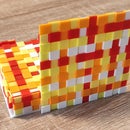
The best result (the best diffusion) I have obtained with the 4mm thick dome, using “rectilinear” 100% infill and, very important, with "fuzzy skin" option. The material I used is a transparent PETG filament.
Additionally, as you will see in the lamp operation video below, an interesting optical result has emerged due to the 3D printing of the semi-transparent hemisphere: the LED colors travel along the hemisphere's meridians. This phenomenon is more apparent in the video. To ensure uniform light diffusion, I nonetheless attempted to create a hydrophilic cotton diffusion layer, which yielded satisfactory results. However, I ultimately opted for the original version as I am drawn to the luminous meridians effect :)
The electronic schematic is above.
A time-consuming part was also the mounting the LEDs on the support. Otherwise, everything was very simple, just some soldering, gluing and assembly. I put a few drops of hot glue here and there for better fixing.
I tried to take some relevant photos of the assembly process, which you can see above.
Step 5: The Software
I mentioned in the introduction about the two programs I made for this lamp.
Here is a little more detailed explanation:
- Golden ratio color palette generator: This program uses the golden ratio to generate a series of colors that are pleasing to the eye. The colors are then faded into each other to create a smooth transition.
- Predefined color palette fader: This program uses a set of predefined color palettes that are faded into each other to create a variety of different lighting effects.
Both of these programs can be used to customize the lighting of the lamp to suit your personal preferences.
I. I used the Fibonacci sequence and golden ratio to uniformly distribute LED modules on a hemisphere, so I thought of using the golden angle to generate a color palette and display it on the LED modules.
But first, what is the golden angle?
The golden angle, also known as the divine angle, is a beautiful and mathematically significant angle of approximately 137.5 degrees. It is derived from the golden ratio, a ubiquitous constant found in nature, art, and design. The arrangement of leaves, petals, and seeds in plants often follows this angle, maximizing packing efficiency and sunlight exposure. The golden angle also finds applications in art and design for creating beautiful compositions.
So, we can use the golden angle to select colors from the color wheel for aesthetically pleasing and harmonious color schemes.
The idea is to distribute colors around the color wheel at intervals of the golden angle (approximately 137.5 degrees) to create a balanced and visually appealing palette. But we are working within the constraints of the FastLED library, which uses one-byte values (0-255) for hue, saturation, and value. Anyway, we can still apply the golden angle concept. We’ll just need to adjust the calculation to fit within the 0-255 range.
To apply the golden angle to color selection, we can follow these steps:
- Select a Base Color: Choose a base color using FastLED’s hue range (0-255).
- Calculate Golden Angle: Add the golden angle (approximately 137.5 degrees) to the hue of our base color. If the result is greater than 255, subtract 256 to bring it back within the 0-255 range.
- Repeat: Continue adding the golden angle and adjusting if needed to keep the values within the 0-255 range.
Here's a simple example in pseudocode:
base_color = 100  # Replace with your chosen base color in the range 0-255
golden_angle = 137.5  # Adjust as needed

for i in range(number_of_colors):
    next_color = (base_color + golden_angle * i) % 256
    # Use 'next_color' for setting the hue in your FastLED application
In the final version of the program, the base color and the number of colors in the palette are randomly selected every 10 seconds, and the transition from the old color palette to the new one is gradual, as I did in my triangular pixels LED clock project. The program is attached below, and further down, in the next step, you can see a short video of the lamp in action.
II. In the Palettes.h file i have a bunch of predefined color palettes. Every 10 seconds, the program randomly selects a new color palette from the predefined palettes , displays it, and then gradually fades into the random next one. The operation is remarkably simple, yet effective (this is an example of how to use the code from here) This program can be found also attached below.

Step 6: The Video
Step 7: Closing Words
I hope you enjoyed reading my article! I hope I have inspired you to build your own lamp, or perhaps I have given you an idea and we will see something different but based on this build. All I have to do is wait for your reactions and if I can, I am happy to answer your questions.
Thank you for your time and interest!

Participated in the
Anything Goes Contest


