

Introduction: 3D Adventurer [Equatorial Mount for DSLR]
![3D Adventurer [Equatorial Mount for DSLR]](https://content.instructables.com/F1S/A6MH/KA6SE5CW/F1SA6MHKA6SE5CW.jpg?auto=webp&fit=bounds&frame=1&height=1024&width=1024auto=webp&frame=1&height=300)
![3D Adventurer [Equatorial Mount for DSLR]](https://content.instructables.com/FWE/LSW2/KA6SE5QX/FWELSW2KA6SE5QX.jpg?auto=webp&fit=bounds&frame=1&height=1024&width=1024auto=webp&frame=1&height=300)
![3D Adventurer [Equatorial Mount for DSLR]](https://content.instructables.com/FR2/ASI2/KA6SE677/FR2ASI2KA6SE677.jpg?auto=webp&fit=bounds&frame=1&height=1024&width=1024auto=webp&frame=1&height=300)
![3D Adventurer [Equatorial Mount for DSLR]](https://content.instructables.com/FAQ/WY7W/KA6SE67A/FAQWY7WKA6SE67A.jpg?auto=webp&fit=bounds&frame=1auto=webp&frame=1&height=300)
![3D Adventurer [Equatorial Mount for DSLR]](https://content.instructables.com/FM7/D61A/KA6SE67B/FM7D61AKA6SE67B.jpg?auto=webp&fit=bounds&frame=1auto=webp&frame=1&height=300)


As a big fan of astrophotography and 3D printing I had to build my own equatorial mount for my DSLR.
For this project I used Fusion 360 to design all the pieces.
With this instructable you can design your own or you can use my STL files and follow the assembly tutorial.
Enjoy!
Supplies
Electric:
- 1x stepper motor 28BYJ-48 5V
- 1x ULN2003 driver board
- 1x Arduino (I used nano but every arduino will work)
- 2x push button (I used a double momentary toggle switch)
- 2x led 3mm (1x Orange + 1x Red)
- 1x DC jack adapter
- wires, soldering iron,
Mechanic:
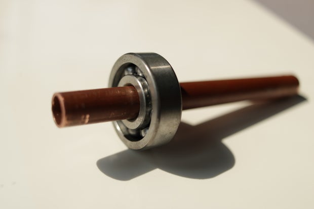
- 2x ball bearing (10-30-9)
- 1x metal tube 105~110 mm long with external diameter according to the bearing (here 10 mm)
- 3D printer + PLA
- Screws + nuts (I used M2.5 kit)
- 1x M8 threaded rod + M8 nuts
- Heavy stuff
Others:
- 1x DSLR camera + lens
- 1x Tripod (mine is a Manfrotto Compact Advanced)
- 1x Camera ball joint
- 1x Kodak screw to mount the ball joint
- CAD software if you want to modify the files (fusion 360 is free for students)
Step 1: Purpose

As you know, Earth is rotating, so it is not easy to photograph stars because they leave star-trails.
In astrophotography, we use the "500 Rule" it allows to take pictures of the night sky without noticeable star trails: divide 500 by the focal length of your lens and you will obtain the maximum exposure time. However, with the crop factor of my DSLR it turns out to be the "300 Rule". My lens is a Canon 24mm f2.8 so according to the rule: 300/24=12.5 I can only shoot stars during 12.5s and that is very short to capture enough light from them.
The device I made is tracking stars, that allows to get rid of that rule and shoot as long as we need.
Fortunately the rotation of the Earth is well known, the axis is passing through the north celestial pole and the rotation speed is 1rev/23h56min4s (stellar day)
With that we can create a device that turns on a parallel axis and at the exact opposite speed as the Earth.
It is called "equatorial mount", it is commonly used with a telescope because with only 1 motor it tracks stars.
Some of them are big and really powerful in order to rotate enormous telescopes but some others are small carrying only a DSLR that is what I wanted to make.
It can also be useful to make timelapse according to earth's rotation.
Step 2: Designing


First, 1rev/23h56min4s is slow, very slow. And for my star tracker I wanted as few gear wheels as possible in order to reduce play in the mechanism that is why I didn't make a planetary gear. I decided to make a simple gear reducer with only 2 wheels, one with 10 teeth and the other with 60 teeth, that way, it divide the speed by 6 and multiply the torque by 6, perfect !
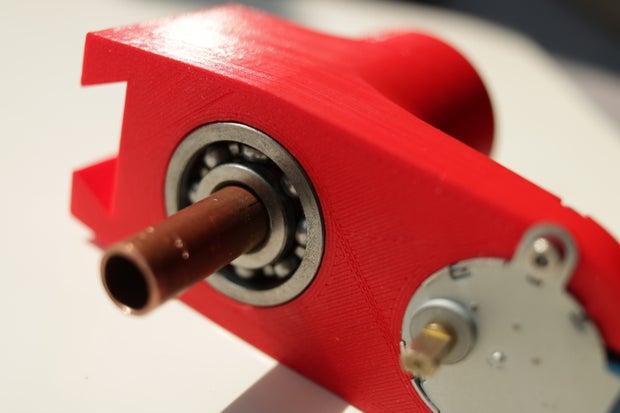
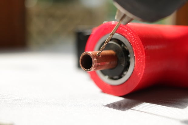
The main shaft is made from a copper tube the material is not very important but it must be a tube, you will understand why later. It has a diameter of 10mm because I had some 10-30-9 bearings (those may be oversized but it results in a very reliable revolute joint)
I used a 5VDC 28BYJ-48 stepper motor, which is not very powerful but with the gear ratio it should be enough
As I live in the north hemisphere at roughly 45° latitude I tilted the Manfrotto socket by 45° the adjustments will be ensured by the tripod head.
I designed all the parts using Fusion 360.
on the 2nd picture, pieces with a "*" are not 3D printed.
Step 3: 3D Printing

I 3D printed all the parts on my Creality Ender 3 with those settings:
- Cura slicer
- ICE filament 1.75mm
- nozzle 210°C
- bed 50°C
- 20% infill (gyroïd)
- 0.16mm / 0.2mm layer height
- no supports
- Ø 0.4mm nozzle
- 40mm/s
the total printing duration is roughly 12h.
Here is the Cults3D link to the files: HERE (.stl and .f3d)
Step 4: Prototyping
23h56min4s is equal to 23.9344444...h
1rev/23.934444h on the main shaft --> 1rev/3.989074h on the motor shaft
4076steps/rev on the motor --> 1 step every 3.523s [3.523225s]
The DSLR stays motionless during exactly 3.523s so according to the 500 and 300 Rule : the equatorial mount will work with lens below 142mm focal length on a full frame and below 85mm on a crop sensor.
In order to drive the motor with 4076 steps, there is this Arduino library by tyhenry.
Here is the code to put in the arduino board if you live in the northern hemisphere.
/*<br>Sketch by SimonRob
3D printed equatorial mount for DSLR
Instructables
*/

int buttonA1 = 0;
int buttonA2 = 0;
int ledOrange = 4;
int ledRed = 5;

#include <CheapStepper.h>

CheapStepper stepper;

void setup() {
  pinMode(A1, INPUT);
  pinMode(A2, INPUT);
  pinMode(ledOrange, OUTPUT);
  pinMode(ledRed, OUTPUT);
}

void loop() {

buttonA1 = digitalRead(A1);
buttonA2 = digitalRead(A2);

if (buttonA1 == HIGH){
  buttonA1 = digitalRead(A1);
  buttonA2 = digitalRead(A2);
  digitalWrite (ledOrange, HIGH);
  digitalWrite (ledRed, LOW);
  stepper.step(false);
  delay(6);
}
if (buttonA2 == HIGH){
  buttonA1 = digitalRead(A1);
  buttonA2 = digitalRead(A2);
  digitalWrite (ledOrange, HIGH);
  digitalWrite (ledRed, LOW);
  stepper.step(true);
  delay(6);
}
while((buttonA1 == LOW)&&(buttonA2 == LOW)){
  buttonA1 = digitalRead(A1);
  buttonA2 = digitalRead(A2);
  digitalWrite (ledOrange, LOW);
  digitalWrite (ledRed, HIGH);
  stepper.step(false);
  delay(3523);

}
}
the member videoenquirer modified the previous code for the southern hemisphere :
Attachments

Step 5: Assembly
- Screw the motor in place with 2x M2.5 screws + nuts

- Hammer the bearing on the tube, 20mm from the end
- Place those in the corresponding hole of the main body (red piece)
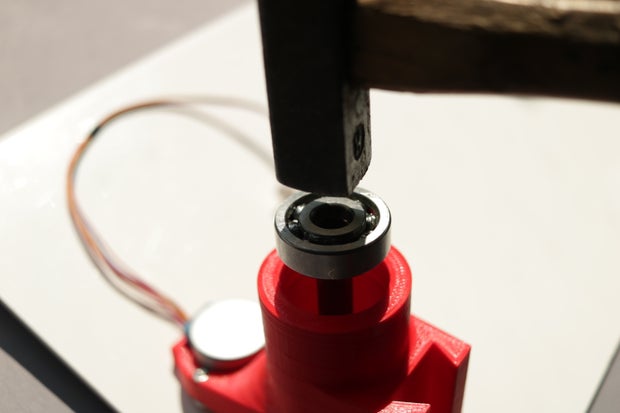
- Hammer the second bearing on the top
- Place a washer or anything that can be a spacer here
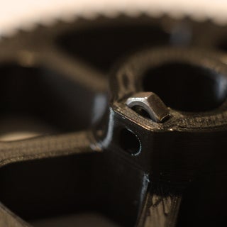
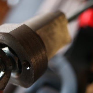
- Insert 4x M2.5 nuts where it is needed (here is the example on the big gear wheel)
- Screw the big wheel and the support on the tube, tight them enough to make a mark on the tube
- Remove those 2 pieces and drill 2 holes at the marks
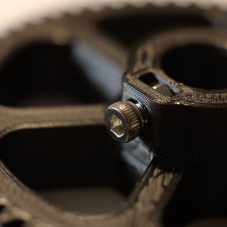
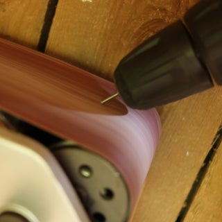
- Sharpen the end of 2 screws
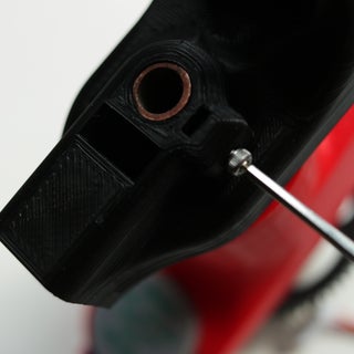
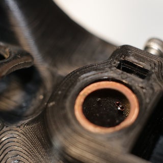
- Screw the big wheel and the support on the tube
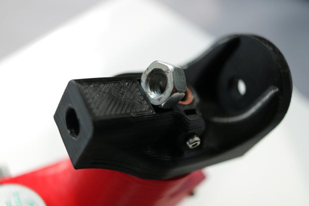
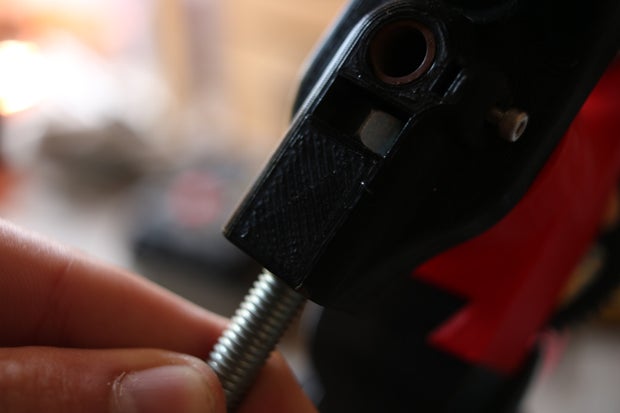
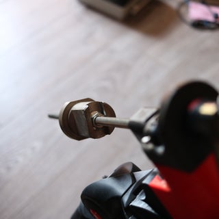
- Insert the M8 nut into the support piece
- Screw the M8 threaded rod
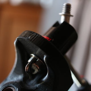
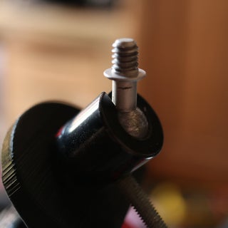
- Screw a camera ball joint with a Kodak screw
- Add counterweight on the threaded rod to balance the mass of the DSLR


Step 6: The Controller
Once printed, screw in place the two PCB (Arduino + ULN2003 driver) and place the components in the box.

Solder wires according to this schematic:
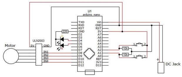
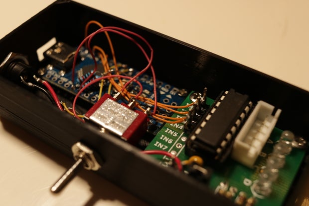
Then plug the motor and clip the lid on the box
Step 7: How to Use It?

- Place the star tracker on the tripod (tube pointing to the north).
- Screw the DSLR on the ball joint, and add the counterweights on the other side.
- Remove the small gear wheel from the motor to release the axis.
- Then adjust the counterweight to balance the rotating part, and put back the small gear wheel.
- Look into the tube and adjust the head of the tripod the see the North Star into it (you can also use a laser through the tube).
- Power on the equatorial mount and enjoy !
Step 8: Astrophotography
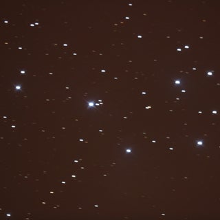
Here is my first photography with the mount :


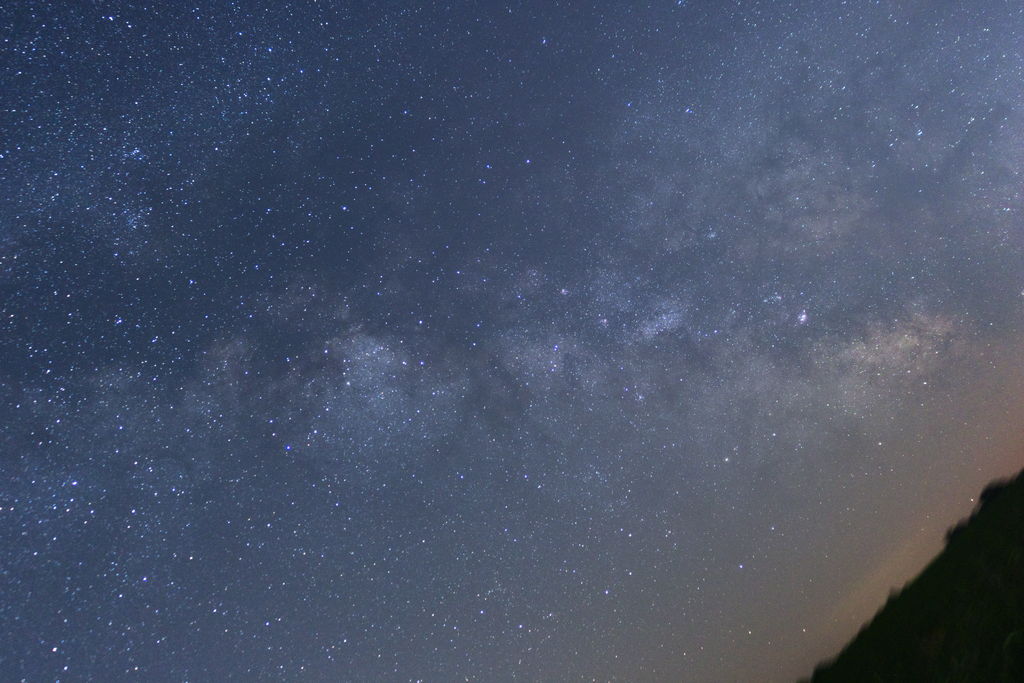
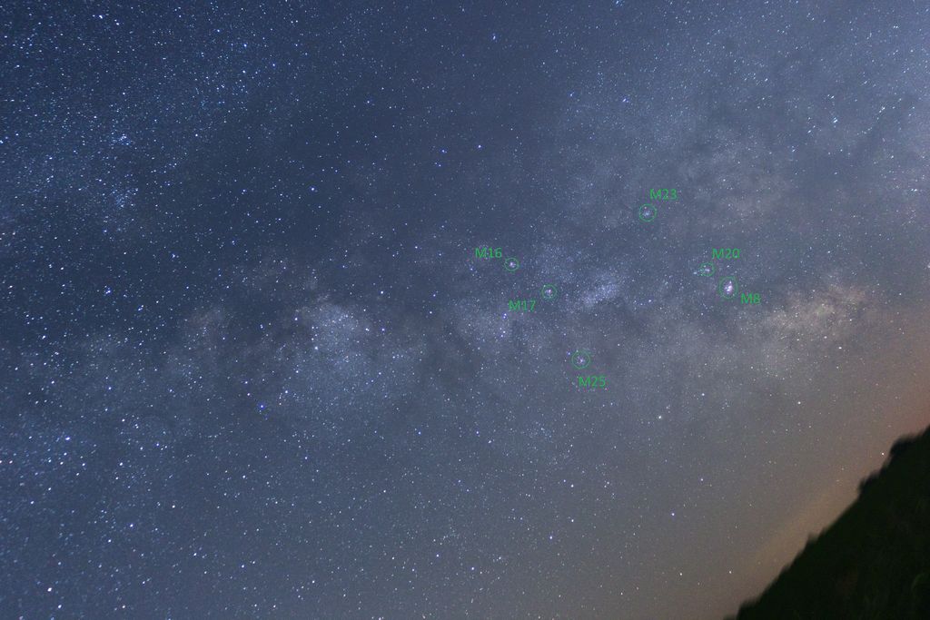
Here is a picture of th milky way,
Canon 750D, Equatorial mount, Canon 18-55mm stm (at 27mm), f/4, iso1600, 196s
You can see that even at 196s exposure, stars stays dots (except in the corners due to chromatic aberations) however there is a motion blur on the trees. If you want them sharp too, you will have to add a motionless picture of your foreground and mix those into Photoshop or Gimp.
on the picture we can easely notice some deep sky objects:
I also practice astrophotography with a telescope, you can see my photos on Instagram ;)

First Prize in the
Space Challenge


