

Introduction: Modular & Expandable Bluetooth Speaker System


Hello, 👋
I’m Lewis, and this is DIY Machines - my little outlet where I get to show you step-by-step how to build your own awesome maker projects. Today I’ll be going over how to make this modular and portable bluetooth speaker system with a couple of awesome tricks up its sleeve.
At its core is the main speaker - everything is contained in this box including the Lithium Ion batteries, recharging circuit, bluetooth receiver and amp. You'll also find both a standard USB and USB C port to recharge your other devices.
This is where it gets cool though: Assemble the second (super cheap) speaker for a louder system and it’s connected as simply as sitting it on-top. Magnets hold it in place whilst the Pogo pins form the electrical connection.
Why did I design it like this? We’ll you can face the second speaker in the same direction for increased volume, face it sideways for a wider sound stage or back to front for when it’s in the middle of a group.
This also lets you choose which modules you take with you when you head out from home. Take just a single one when you head to the beach, or ask a friend to throw the second speaker module in their rucksack to bring it with you.
And when it gets later in the evening why not add the funky disco light module on top to light up the evening whilst you listen to tunes? 🪩
This one is themed after everyone’s favourite plumbers. Don’t worry though, I’ve included an alternative dialled down design should you not care for Italian servicemen. 😉
I’ll explain in detail below everything you need to build your own speaker and as a bonus - towards the end of the Instructable I’ll show you how to add the disco light pipe.
Step 1:
I have written out everything you need to know in this Instructable when it comes to making this speaker. I also love making videos so have made one which you will find above. Consult one or the other but you can't go far wrong if you follow both.
I recommend taking a look at the speaker in the intro of the video before carrying on down through this Instructable - though its not compulsory!
All the 3D model files are attached to the relevant steps (as STL files), wiring diagrams are included where appropriate and the occasional nugget of advice is hidden and imparted throughout. Enjoy! 🙂
Step 2: BOM (What You'll Need)
To build some speakers of your own you will need a few items. Below I have listed them out along with links to where you can find them on Amazon.
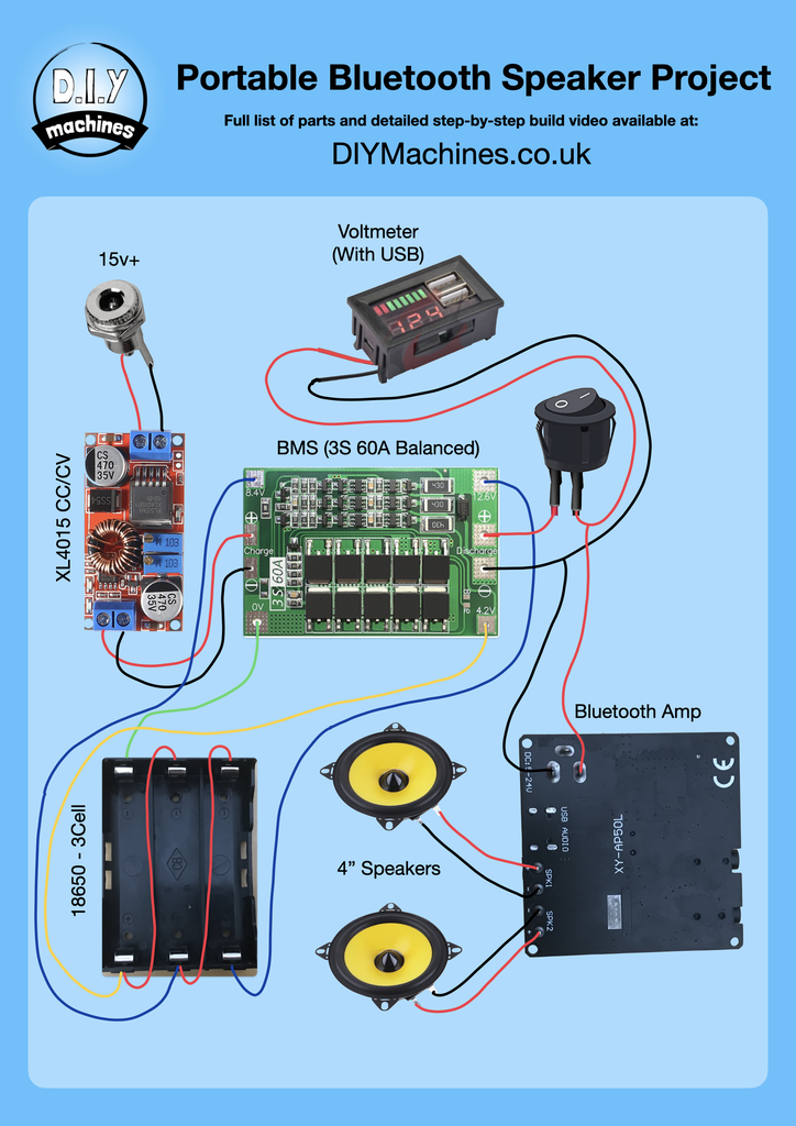
- BMS 3S 60A: https://geni.us/BMC-3S-60A
- CC/CV Buck Converter XL4015 (x1): https://geni.us/XL4015-CC-CV
- Pogo Pins (2mm spring head & 5.5mm shaft length) (x2): https://geni.us/PogoPins75-55
- 3 Cell 18650 Battery Holder (x1): https://geni.us/3s-18650-Holder
- Quality 18650 Lithium Ion Batteries from a reputable source (x3): Please, for safety, don’t get the cheapest ones you can find online!
- Bluetooth Amp: https://geni.us/Bluetooth-AMP
- Voltmeter / USB PSU (x1): https://geni.us/Voltmeter-with-USB
- DC Barrel Connector (x1): https://geni.us/HighAmpDCBarrel
- Power Switch (x1): https://geni.us/Power-Switch
- 4” Full Range Speakers - They don’t have to be yellow! :) (x1 or 2): https://geni.us/4-Inch-Speakers
- Power supply (15v+ and at least 3Amp):
- Magnets (12x3mm): https://geni.us/12x3mmMagnets
- Bolts (M4x5mm) (x??): https://geni.us/M4-Bolts
- Filament: https://www.3djake.uk
- PCB: https://www.pcbway.com/project/shareproject/3D_Printable_Modular_Bluetooth_Speaker_System_3df5b9d9.html
- Disco Light: https://geni.us/USB-Disco-Light
I have also put together a kit of Electronics part to help sourcing the correct components easier. They are available on my internationally shipping Etsy shop: https://www.etsy.com/uk/listing/1492616468
Step 3: Warning - LiPo Cells

Safety Warning: Lithium batteries are very dangerous if not treated correctly. They can pose a significant explosion and fire hazard. Please consult a professional before attempting the following. I have tried my best to ensure a safe design - but I am not a trained professional.
Step 4: 3D Printing Main Housing

For this step you'll need:
- 3D printed 'Speaker Housing - Main.stl'
The first part to 3D Print is the main housing. I have attached the STL files for each 3D printed part to the relevant step here on Instructables.
This part, like all the others for this project except one, is designed to print without any supports. I added a brim to ensure good adhesion whilst using a 0.6mm nozzle width and 0.3mm layer height for speed.
The greater the quantity of infill and perimeters used the better the sound quality.
Attachments

Step 5: Preparing & Installing the 1st Speaker


For this step you'll need:
- One of your 4" speakers
- 15cm of wire (x2)
- Four of your M4x5mm bolts
Solder one end of each wire to the terminals on the rear of the speaker.
This is then screwed into position inside the 3D printed housing using the first four of your bolts.
Step 6: Magnetic Attraction


For this step you'll need:
- 12x3mm disc magnets (x8 - four for this step and four in the next)
- Super glue or 'hot snot' (Hot melt glue)
The separate modules of the project are kept together with the help of magnets. You don’t need to use these but it does help keep the modules together and has a lovely tactile feel when you join and separate the parts.
Start by mark the same pole with a permanent pen on eight magnets as shown in the animation above. (It doesn't matter if this is the north or South Pole as long as you're consistent).
Glue four of the marked magnets into the recesses of the main housing with their markings hidden inside the print so you can't see them once installed.
Step 7: The Second Housing & Magnets


For this step you'll need:
- 3D printed 'Speaker Housing - Slave.stl'.
- The other four marked 12x3mm disc magnets
- More glue
We can then 3D print the second speakers housing (attached) and then add four more magnets to the inside bottom of the print with their dot’s showing this time. (The bottom face is the side with the protruding feet on it and the recess for the PCB to inserted inside later.).

Step 8: Adding the '?'


For this step you'll need:
- Super Glue (preferably)
- 3D Printed 'Question Mark.stl'
Whilst we’re glueing things, let’s 3D print the optional decorative question mark elements in white and fix these to the outside faces of the boxes. You’ll need two sets for each speaker. Pay attention to the orientation of the speakers as you glue the question marks on!
Set aside the box without a speaker for now whilst we concentrate on the main module.
Attachments

Step 9: Print and Assemble Rear Panel


For this step you'll need:
- 3D Printed 'Rear Cover - Main.stl'
- Voltmeter
- Female DC Barrel connector
- Power switch
The Rear Cover is the only part that will require supports (on the build plate only) when printing.
The three electronic devices are then inserted with the power connecting being secured with a nut from the reverse side and the remaining two being snap fitted into place.
Attachments

Step 10: The PCB


We’ll be soldering our components to a custom PCB I designed to help make everything incredibly easy to assemble. You can follow the links in the BOM above to buy one if you wanted to - it drastically cuts down on wiring and holds everything in just the right place.
Of course, if you don’t want to use the PCB you’ll find a wiring diagram attached above for you to build your own circuit.
The PCB actually contains three separate circuits. There are two 'daughter' boards if you like in the corners. To separate them we can use a saw to cut down the thick white lines.
Step 11: The Battery Management System (BMS)


For this step you'll need:
- PCB (Printed circuit board)
- BMS (Battery management system)
We’ll start by adding the BMS. Align it with the pads as labeled on the PCB and BMS.
Apply plenty of heat (I boosted my soldering iron to 400ºC+) and then melt your solder into the solder pads ensuring it is sufficiently hot to flow well down through the hole and onto both the lower pad on the main PCB and the pad on the BMS.
This work well as long as you ensure you have sufficiently heated both pads.
Step 12: 18650 Cell Holder


For this step you'll need:
- PCB (Printed circuit board)
- 18650 Battery Holder
The battery holder is inserted on the other side of the BMS whist ensuring to properly align the positive and negative ends This is then soldered to the PCB back on the first side.(Same side we soldered the BMS to).
Step 13:


For this step you'll need:
- PCB (Printed circuit board)
- Bluetooth Amplifier
Flip the board over again to the same side as the battery holder. Position the bluetooth amp over its outline and then solder this from the first side again. In the photos above I have circled the points in yellow that need soldering.
Step 14: Soldering Voltmeter and Switch


For this step you'll need:
- PCB (Printed circuit board)
- The half assembled rear panel from earlier
Connect the wires for the Voltmeter cable and Switch to the appropriately marked points on the PCB. They should be inserted from the side with the BMS and soldered on the side with the Amp and Battery Holder.
Pay particular attention to the positive wires of the Voltmeter - this is not so important for the Switch.
Step 15: Pre-configuring the Buck Converter


For this step you'll need:
- Step down DC to DC converter
- Multimeter
- Power supply the one for your final project)
- Screwdriver (small flat head)
Next up is the step-down DC to DC converter. This needs to be a constant voltage and constant current module to ensure we don’t miss-charge the Lithium Ion batteries. Our BMS protects the batteries from over voltage but it does not limit the charge current. That's th job of this circuit (alongside stepping down the voltage).
Before we solder it we need to set an appropriate output current and voltage. To do this connect its input to our 15v power supply via the barrel connector and grab yourself a multimeter.
Set you multimeter to measure voltage and connect it to the output pins of the module. Rotate this small potentiometer on the left (the one with a black arrow pointing to it in the above images) until you are reading 12.6v. (That’s the 4.2v max output of our batteries times by the three cell we’re using). 🙂
It takes about 20 turns to go from one end of the potentiometer travel to the other so don’t be alarmed if you have to keep turning. Turn clockwise to increase and anti-clockwise to decrease the reading.
For the current level you will need to check the amp hours of the cells you are using. On mine you can see it shows 3000 Mah which is 3 amps (for one hour). We can charge at this rate which is also known as 1C. What is C? Well, if your battery is 3 amp-hours like mine... 1C is 3 amps. 0.5C is 1.5amps and 2C would be 6amps.
But to increase safety and battery longevity I’ll set mine to 0.5C (which is half of the batteries capacity) so in my instance this will be 1.5amps.
To set this, prepare your multimeter to measure current - this usually involves inserting the test leads into different terminals on the metre. Because it is a constant current power supply we don’t need to worry about shorting the circuit. The LED at the top will turn red to indicate it is now having to limit the current. Turn the other small potentiometer until you reach the desired current limit.
Done 👍🏼
Step 16: Connecting Buck Converter


Turn over the board and use some snips to trim the metal legs found on the underside of the circuit board so that it can is closer to the main PCB in a moment.
Solder this board into place onto the main PCB we've been assembling being sure to line it up with the correct pads.
I know it’s not exactly best practice to bridge the connection with solder but it will adequate for our needs.
Step 17: Attaching DC Barrel & Speaker


We can also now solder the leads from the DC barrel connector to the PCB ensuring you respect the polarity.
Solder the speakers wires to the contact points as well. The polarity you attach the speaker wires to does not strictly matter - though you'll need to remember which one you connected to which terminal (positive and negative) and match this with the second speaker later.
Step 18: Add Batteries & Test


For this step you'll need:
- 18650 LiPo cells (x3)
- A mobile phone or similar to connect to bluetooth and play music
Add your batteries (being careful to check the polarity), plug in the power supply, switch it on. The batteries should now be recharging.
Take your speaker on a test spin by connecting your phone via bluetooth (it should show up as a device called 'XinYi').
If it works, unplug the power supply and the tunes should keep playing from the battery power. If so let’s carry on - if not check your work so far for errors. I also recommend keeping an eye on your Li Ion batteries for signs of swelling or overeating on your first few uses and charging cycles.
Step 19: Assembling the Pogo Inter-connect


For this step you'll need:
- Your rectangular cut-off PCB
- Two Pogo Pins
- The second speaker
- 6x Bolts
- 15cm wire (x2)
- 3D printed 'Pogo Cover - Male.stl'.
Let’s prepare the first of our two mini circuit boards for our interconnect between the speakers. Solder two pogo pins to the pads on the rectangular PCB and then two 15cm wires to the wire points so that the wire exits out the opposite side to the pins.
3D print the male pogo cover and pass the wires through the central cutout with the two round plastic protrusions facing the PCB. The other end of the wires can now be attached to the second speaker.
This speaker is then installed in the second housing using four of our bolts, then the PCB is held in position using the 3D printed cover and another two bolts. (The cover will only accommodate the PCB in one orientation so if it doesn’t fit try the other way around. This is to help force the correct polarity arrangement.)
Attachments

Step 20: Assembling Remaining PCB


For this step you'll need:
- Your squarer cut-off PCB
- Three bolts
- 3D printed 'Pogo Cover - Female.stl'
- Two 15cm long wires
For the other side of this connection we can solder another pair of 15cm long wires to the solder points on the remaining mini PCB with the wires entering from the reverse side.
These wires pass through the 3d printed female pogo cover which is then held into place with three bolts.
The wires are then tinned and clamped into position in the screw terminals of the bluetooth modules outer two connections. Remember taking note of the polarity when connecting the first speaker? That's what you need to duplicate with this speaker know when connecting the wires to the screw terminals.
Attachments

Step 21: Completing the 'Master' Speaker


For this step you'll need:
- Four bolts
- 3D printed 'Battery Lid.stl'
Our main PCB is then mounted on the reverse of the main speakers rear cover (on the four stand offs) with four bolts.
This entire rear assembly is in turn fitted to the speaker housing with another four more bolts.
The volume control knob is push fitted onto of the Bluetooth amp.
The battery lid is then printed and should be a snug fit without requiring any bolts - but if yours is loose it can be secured with two more bolts. You bought plenty of bolts right?
Attachments

Step 22: Completing the 'Slave' Speaker


For this step you'll need:
- Four bolts
- 3D printed 'Rear Cover - Slave.stl'
The rear cover of the second speaker is also fitted with four bolts.
You may be wondering why I use so many bolts. I used to glue my project together but then began to realise this made future repairs, upgrades and revisions much trickier. Now parts can be re-used and repaired when required.
There you go, that’s the main speaker system complete. The second speaker should connect and play automatically in any orientation when sat on top of the main speaker. How cool is that!?
You can recharge your other devices from the USB ports when the speaker is powered on.
Attachments

Step 23: Preparing the Pipe Light Base


For this step you'll need:
- 3D printed 'Light Cover.stl' and 'Light Base.stl'
- Two magnets
- Two washers
- Glue
- Some paint (if you want to paint it that is).
To add some more party vibes to your portable speaker system we can also build the disco light pipe add-on.
We’ll start by printing the main base of the disco module and its cover. I did these in 3D Jakes Lumberjake filament and then painted the grouting areas in black. We can then glue two magnets into the rear of the base and a couple of washer on the rear of the cover. The polarity of these two magnets does not matter.


Step 24: Assembling the Pipe


For this step you'll need:
- 3D printed 'Pipe.stl' and 'Pipe-Cable Cover.stl'
- The disco light
- Glue
I printed the two parts of the pipe in green PLA before glueing the light inside the large tube ensuring it’s power connection faces out of the pipes access port.
The pipe and disco light is glued into place on top of the main housing.
The USB cable is then attached and passed through into the base. Before we use super glue to fix the cable enclosure into place to conceal the cable.
If you want to use magnets to attach it to the other speakers you’ll need to add some into the base of the disco light housing and some in the top of the second speaker. There are recesses for this already provided for you.
Ensure you use the correct polarity orientation with the magnets in the first speaker (just pop some onto then transfer these into the base of the disco light - then pop some on the bottom of the disco light and transfer this arrangement to the top of the second speaker).
to power your disco module just remove the magnetic backdoor and connect the USB cable to the main speaker unit. Their is a notch in the cover which will allow you to reattach it whilst the cabe passes through the notch.


Step 25: Project Complete!
Well done. I hope you enjoyed following along and thank you for making it through to the end I know I can be a bit wordy sometimes! 😆
Have the best of fun with your speaker and I look forward to sharing my next project with you soon. Subscribe here on Instructables or over on my Youtube channel to keep up-to-date.
Take care, do some good, and ciao for now. 🙂
Lewis

Grand Prize in the
Battery-Powered Contest


