

Introduction: PORTABLE Space Trash Game Console


Greetings and welcome back.
Here's something fun: a portable pocket game console that incorporates an XIAO ESP32C3, an XIAO Expansion board, and some custom 3D printed parts to run the beloved space trash game.
The XIAO ESP32C3 microcontroller, which powers this project, pairs with an XIAO expansion board. The XIAO ESP32C3 board controls an OLED display placed on the XIAO expansion board.
Three external buttons were added, one of which is for fire and the other two for up and down control of the spacecraft.
The whole Instructables is about the construction process of this build, so let's get started.
Supplies
These were the components used in this build:
- XIAO Expansion Board
- XIAO ESP32C3
- Breadboard
- Push Buttons
- 1K Resistors
- Prototype PCB
- 3D-printed body
Step 1: XIAO EXPANSION BOARD: XIAO ESP32C3


An XIAO ESP32C3 microcontroller and an XIAO extension board manufactured by Seeed Studio comprised the heart of this project.
It comes with rich peripherals that include an OLED, RTC, SD Card Sot, passive buzzer, reset/user button, 5V servo connector, and Grove connector for pairing multiple Grove devices with XIAO.
We can power the entire setup using any Li-ion or LiPo cell thanks to its integrated Li-ion charging circuit.
If you would like to get one for yourself, here is the link to its page.
https://www.seeedstudio.com/Seeeduino-XIAO-Expansion-board-p-4746.html
The battery input section and the SSD1306 OLED were the two major elements we used in the expansion board.
The OLED screen is connected to the XIAO's i2c pins, allowing us to control it directly without requiring additional connections.
the Adafruit's SSD1306 library can be used with the OLED screen, but you can also use the u8g2library.
As for the microcontroller, we are using the XIAO ESP32C3, which is a IoT mini-development board based on the Espressif ESP32C3 WiFi/Bluetooth dual-mode chip. ESP32-C3 is a 32-bit RISC-V CPU, which includes an FPU (Floating Point Unit) for 32-bit single-precision arithmetic with powerful computing power.
This board comes with an external antenna to increase the signal strength for wireless applications. It also has a small and exquisite form-factor combined with a single-sided surface-mountable design.
It is equipped with rich interfaces and has 11 digital I/O that can be used as PWM pins and 4 analog I/O that can be used as ADC pins. It supports four serial interfaces, such as UART, I2C and SPI. There is also a small reset button and a bootloader mode button on the board.
You can check out Seeed Studio's brief product introduction for the expansion board and XIAO ESP32C3, which includes a ton of information, by clicking the link below.
https://wiki.seeedstudio.com/Seeeduino-XIAO-Expansion-Board/
https://wiki.seeedstudio.com/XIAO_ESP32C3_Getting_Started/
Visit Seeed Studio to get a wide range of services, including 3D printing, PCB/PCBA, and microcontroller/module services.
Step 2: BASIC SETUP


Setting up a basic breadboard version of the project, which consists of three push buttons connected to one 1K resistor each between VCC and GND, is the first phase or level. When the button is pressed, a value is obtained at the GPIO pins, which is read by the XIAO MCU and triggers it to execute the XYZ set in the code. The middle pin between the resistor and switch is linked to the GPIO of the XIAO MCU.
Follow the added wiring diagram for this setup.
We added the main code to the XIAO EXP32C3 board and tested the system.
D0 is for fire, D1 is for the up button, and D2 is for the down button.
Step 3: CODE
Here's the code used in this project, and to run this code, you first need to install the U8g2lib library from the below link.
Attachments

Step 4: LEVEL 2


- We used a 55 x 35 mm prototype board for Level 2 of this project and added three push buttons to it: two 6 x 6 mm push buttons for up and down, and one 12 x 12 mm push button for fire.
- Next we added Three 1K Resistor with each push button.
- The resistor and push button leads were then soldered together, and five wires (VCC, GND, D0, D1, and D2) were also connected.
- Next, we use a soldering iron to join the wires of the prototype board to the XIAO VCC, GND, D0, D1, and D2 terminals on the back side of the XIAO expansion board.
Step 5: POWER SOURCE


We attached a 3.7V LiPo cell via the JST connector to the expansion board after soldering the Switch PCB and the expansion board together.
Our little 100mAh 3.7V Li-Po cell provides 0.37Wh of power, which is more than enough for this tiny portable setup.
Step 6: 3D DESIGN


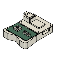
After assembling the Switch PCB and XIAO expansion board, we model both components in Fusion360 and create a robust enclosure that holds the XIAO, which is connected to a battery, and the switch PCB.
We incorporated the XIAO expansion board on top and the switch PCB slightly below it, adhering to the standard MO of the game controller. We also built a frame-like holder with mounting holes for screws to be used when the circuit is installed.
Once the design was finished, we exported the mesh file and used a golden yellow PLA material to 3D print it using an Ender 3 printer with a 0.4mm nozzle and 25% infill.
Step 7: ASSEMBLY PROCESS


- In order to complete the build, we connected the JST connector of the LiPo cell into the expansion board first, and then we placed the LiPo cell into the 3D printed base.
- Next, we position the switch PCB and expansion board on the expansion board in their proper locations.
- we then attach the Switch PCB and XIAO expansion board to the 3D printed housing using six M2 screws.
The Pocket Game console is now complete.
Step 8: RESULT


Here's the result of this small build: a completely functional portable game console, loaded with the classic Space Trash game from old Nokia phones.
The ESP32C3 chip is the reason that this setup functions flawlessly. Although the code is somewhat lengthy, the chip's processing capability allows it to do such tasks with ease and without any issues.
With its compact size of about 85 x 60 x 25 mm, this device is very lightweight and portable, making it the perfect choice for trips outdoors.
Because we are utilizing a 100mAh LiPo cell, the battery life of this setup is just one hour. In the future version, we could improve the backup by using a larger capacity battery.
Since this project utilizes a temporary prototype board circuit, the switch PCB also needs to be improved.
The above two points need to be improved in the next version.
Leave a comment if you need any help regarding this project. This is it for today, folks.
Thanks to Seeed Studio Fusion for supporting this project.
You guys can check them out if you need great PCB and stencil service for less cost and great quality.
And I'll be back with a new project pretty soon!


![Tim's Mechanical Spider Leg [LU9685-20CU]](https://content.instructables.com/FFB/5R4I/LVKZ6G6R/FFB5R4ILVKZ6G6R.png?auto=webp&crop=1.2%3A1&frame=1&width=306)


