

Introduction: Quaternion Compass


This instructable explains how to build, and calibrate, a tilt-stabilized compass using an Arduino UNO R3 and an MPU-9250 accelerometer | gyro | magnetometer. [1]
The following options are available for displaying the compass heading | pitch | roll:
- Serial Monitor
- LCD display
- A graphics “compass rose” on your PC screen
Calibration is simple ... three methods are provided:
- Tumble the compass every time at switch-on
- Tumble the compass once and save the results
- Use my “compass_cal” software and save the results
A compass-heading of +/- 2 degrees is possible using my “compass_cal” software.
The estimated cost for this project is $20 USD.
Videos
- “compass_cal” demonstrates my magnetometer calibration software. The user is asked to rotate the compass in 6 different orientations. The results are shown in a rotatable 3D display. The required magnetometer offsets and scale-factors are calculated and presented in a manner suitable for use with cut-&-paste. Compass heading accuracy is within +/- 2 degrees.
- “compass_rose” demonstrates my graphics “compass rose”. The scale rotates beneath the compass needle which is fixed.
- “heading_pitch_roll” demonstrates the compass accuracy at 90 degree intervals. The affect of pitch and roll on the compass heading is also demonstrated.
Images
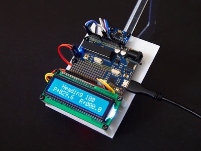
- Photo 1 shows the compass resting on a 30 degree protractor
- Photo 2 shows the output from my “compass_cal” calibration routine
- Photo 3 shows my graphics “compass_rose”
Warning
Do not use this compass in situations involving safety to life, such as navigation at sea.
[1]
Strictly speaking the compass is not tilt-stabilized ... it uses “quaternions” ... but the effect is the same!
Step 1: Circuit Diagram

Photo 1 shows how the Arduino UNO R3, The LCD display, and the MPU-9250 accelerometer/gyro/magnetometer are wired together.
The MPU-9250 must:
- be level when the compass is switched on.
- be clear of any ferrous metals
Step 2: Parts List
The following parts where obtained from https://www.aliexpress.com/
- 1 only Arduino UNO R3 and USB cable
- 1 only serial LCD display
- 1 only MPU-9250 accelerometer/gyro/magnetometer
- 2 only Arduino female-to-female jumper cables
- 6 only Arduino male-to-female jumper cables
The following parts were obtained locally:
- 9 volt battery
- 9 volt battery clip/leads
- Scrap plastic sheet for base
- 12 only threaded nylon spacers
- 20 only M3 x 5mm bolts
The estimated cost for this project is $20 USD.
Step 3: Theory


"Quaternions" are a complex number system that enable us to calculate the attitude and heading of any object relative to Earth in real time. [1]
The MPU-9250 chip contains:
- an accelerometer which knows which way is down
- a gyro which knows how much each axis has rotated
- and a magnetometer that knows which direction is North
If we feed all of this information into a “quaternion” we can calculate our pitch, roll and compass-heading.
Traditional compasses
The compass-heading from a stand-alone magnetometer is only valid if the compass is level ... if we tilt the compass the compass-heading will vary.
These variations may be minimized using standard tilt-compensation formulas. My instructable https://www.instructables.com/id/Tilt-Compensated... demonstrates this technique.
Quaternion compass
This “quaternion” compass uses an entirely different technique ... it simply reports your “pitch” (nose-up), “roll” (right-wing down), and compass-headings in real time. Tilt-stabilization formulas are not required as the compass knows its exact orientation and heading at all times.
For example:
- Flip this compass upside down and the roll will change from 0 degrees to 180 degrees ... the other readings won’t change.
- Place the compass on a 45 degree sloping surface such that the pitch reads 45 degrees and the roll reads zero. Now rotate the compass 90 degrees clockwise ... the roll changes to 45 degrees and the pitch changes to zero because it is now horizontal.
Compass evolution
This compass uses the "Sparkfun MPU-9250 Breakout Arduino Library", https://github.com/sparkfun/SparkFun_MPU-9250_Brea...which was forked from https://github.com/kriswiner/MPU9250
I found that the Sparkfun yaw angle varied whenever I tilted the MPU-9250.
The problem disappeared when I modified the Sparkfun MahonyQuaternionUpdate() function to read: [2][3]
MahonyQuaternionUpdate(  myIMU.ax,              -myIMU.ay,               myIMU.az,
                         myIMU.gx * DEG_TO_RAD, -myIMU.gy * DEG_TO_RAD,  myIMU.gz * DEG_TO_RAD,
                         myIMU.my,              -myIMU.mx,              -myIMU.mz,
                         myIMU.deltat);
Following this change:
- The pitch and roll work as normal.
- The yaw angle no longer varies when the compass is tilted
- The “compass-heading” and “gyro-yaw” track each other 100%.
Some lateral thinking:
- If the gyro-yaw and the compass heading track then why not use the gyro-yaw as the compass-heading?
- If the yaw-angle doesn’t vary when the compass is tilted then traditional tilt-stabilization is not required?
We now have a tilt-stabilized quaternion compass !!!
Notes
[1]
Quaternions are used in applied mathematics to rotate objects in 3D space
There is a lot of mystique about quaternions. From a simplistic viewpoint they are no more difficult to use than say arcsin(Y/X).
Arcsin(Y/X) accepts two inputs (X,Y) and produces one output ... whereas a quaternion accepts multiple inputs and produces four outputs. The reason it is called a quaternion is that the number of outputs is four !!
The following article, “3D Game Programming, Understanding Quaternions”, https://www.3dgep.com/understanding-quaternions/#m... , explains the concept behind quaternions really well.
It starts by rotating a “point” around a 2D circle by continuously multiplying the current location of the “point” by “i” (an imaginary number) ... after four multiplications we are back where we started. This concept is then extended to 3D.
We don’t need to understand the maths ... just how to apply the Madgwick/Mahony quaternion functions.
[2]
Some arbitary rules: [3]
- You can choose any MPU-9250 chip axis to be your North facing axis. I have chosen to use the gyro X-axis.
- Quaternions produce four outputs ... q0, q1, q2, q3
- When the compass is level and pointing North q0, q1, q2, q3 should read 1,0,0,0
The three columns in photo 1 and photo 2 represent the directions that each of the MPU-9250 XYZ axes are pointing when the gyro X-axis is pointing North.
The columns are labelled as follows:
- N = North
- S = South
- W = West
- E = East
- U = Z-axis up
- D = Z-axis down
A negative sign indicates that that particular MPU-9250 axis is pointing in the opposite direction.
The MahonyQuaternionUpdate( ... ) function has 10 parameters ... one for each of the accelerometer, gyro, and magnetometer XYZ axes ... plus a “myIMU.deltat” parameter that controls the timing.
Only two of the possible combinations give a valid output. I chose the last option in photo1 ... these are the values that I have plugged in to the MahonyQuaternionUpdate(...) function above.
[3]
The author of the MPU-9250 library has this to say https://github.com/kriswiner/MPU9250/issues/345
“The Madgwick and Mahony filters (and quaternions in general I believe) work in a right-handed coordinate system. So the data have to be "provided" to conform to this. Thus NED, ENU (the two most common orientation conventions) or even NWU will all work. As long as the sensor data is provided in a manner consistent with the chosen convention.
So first step, the user decides which edge of the sensor board will be pointing to true North when the quaternions read 1 0 0 0. This is one of two absolute references in the system (the other is gravity). Once the board edge facing North is decided (yes, it is your choice!), then it is a simply matter to find out which accel axis point North, no? Then West, then Up. Then the filter should get the data as AN, AW, AU...same for the other two sensors.”
The orientation that I have chosen for this “quaternion compass” is NEU.
Step 4: Software 1 ... "quaternion_compass.ino"
Instructions:
The attached file "QC_files.rar" contains all of the code for this project ... use WinRAR [1] or 7-Zip [2] to extract.
The folder "quaternion_compass" contains all eleven Arduino files and is "ready-to-go". Copy this folder to your Arduino directory and open "quaternion_compass.ino" [3]
Notes:
[1]
WinRAR is available fromhttps://www.win-rar.com/download.html?&L=0
[2]
7-Zip is available from https://www.7-zip.org/
[3]
It is essential that you edit your I2C Wire Library BEFORE uploading the compass code to your Arduino ... instructions for doing this are given in Step 7: Software Installation
Code update
6 March 2020 :
The attached file, "quaternion_compass_new_v8.ino", is essentially the same as "QC_files.rar" but with these differences:
- The code is now contained in a single *ino file.
- Mode selection is easier ... just change one number.
- Sections of the quaternion code have been rearranged for easier reading.
- Soft-iron distortion code has been added.
- The code compiles for both the Arduino Uno R3 and the Adafruit ATSAMD51 Feather M4 Express https://www.adafruit.com/product/3857
Notes:
- The code is 100% compatible with "compass_cal.pde" and "compass_rose.pde.
- The references to "M4" are for the Adafruit ATSAMD51 Feather M4 Express
- The code uses "short" rather than "int" otherwise the M4 doesn't compile.
- The response time is affected by the Kp free variable but at the expense of settling time.
- Kp values above zero appear stable.
- Kp values below zero produce interesting (and possible useful) effects.

Step 5: Software 2 ... "compass_cal.pde"
Instructions:
"QC_files.rar" in Step 4 contains all of the code for this project ... use WinRAR or 7-Zip to extract.
The folder "compass_cal" contains the Processing "calibration" software. Copy this folder to your Processing directory and open "compass_cal.pde" [1]
Notes:
[1]
A list of available COM ports appears on-screen whenever you start "compass_cal" .
If you get a COM port error try changing the number inside the square bracket below from [0] to one of the above.
The following code is found in setup().
  // ----- configure the serial port
  printArray(Serial.list());
  myPort = new Serial(this, Serial.list()[0], 115200);
  myPort.bufferUntil('\n');  // serialEvent() won't trigger until buffer has "\n"
  myPort.clear();
Step 6: Software 3 ... Compass_rose.pde
Instructions:
"QC_files.rar" in Step 4 contains all of the code for this project ... use WinRAR or 7-Zip to extract.
The folder "compass_rose" contains the Processing "compass rose" software. Copy this folder to your Processing directory and open "compass_rose.pde" [1]
Notes:
[1]
A list of available COM ports appears on-screen whenever you start "compass_rose" .
If you get a COM port error try changing the number inside the square bracket below from [0] to one of the above.
The following code is found in setup().
  // ----- configure the serial port
  printArray(Serial.list());
  myPort = new Serial(this, Serial.list()[0], 115200);
  myPort.bufferUntil('\n');	// serialEvent() won't trigger until buffer has "\n"
  myPort.clear();
Step 7: Software Installation

It is essential that you perform this step BEFORE uploading the compass code to your Arduino
Editing your I2C Wire Library
According to the breakout board schematic (photo1) , the MPU-9250 chip has 10K ohm pull-up resistors connected to 3.3 volts on each of the SDA (data) and SCL (clock) lines.
The Arduino, however, has internal pull-up resistors to 5 volts. These pull-up resistors are not required and should be disabled to prevent the I2C lines from rising above 3.3 volts and damaging the MPU-9250.
I recommend editing lines 75 ,76, & 77 in file “C:Users\...\Documents\Arduino\libraries\Wire\utility\twi.c” to read:
// deactivate internal pullups for twi.
digitalWrite(SDA, 0);
digitalWrite(SCL, 0);
These commands could be placed inside the Arduino setup() function following the Wire.begin() function but it is still possible for the I2C lines to rise above their safe voltage level until the code lines are run.
Use a text editor such as Notepad++ when editing any files. Do NOT use a word processor.
Installing the software
Before plugging in your Arduino:
- Disconnect the I2C lines from your Arduino [1]
- Edit your I2C Wire library as described above.
- Download and install the software in Steps 4,5,6
- Upload the “quaternion_compass.ino” sketch to your Arduino.
- Unplug the Arduino.
- Reconnect the Arduino I2C lines.
- Your compass is now ready for calibration
Methods for calibrating the compass may be found in the next Step.
Note
[1]
The reason for disconnecting the I2C SDA (data), and SCL ( lines is that Arduino pins A4 & A5 may be in an output “high” state from a previous project. Disconnecting these wires eliminates the possibility of 5 volts damaging the MPU-9250.
Step 8: Calibrating the Compass


Depending on their orientation with respect to the Earth’s magnetic field, the XYZ outputs from the magnetometer change from +ve to -ve (positive to negative) as the magnetometer is rotated.
If you rotate the MPU-9250 about each axis, the XYZ outputs should each plot a perfect circle centered about the 3D XYZ coordinate (0,0,0) as shown in photo 1 (see calibrated).
Hard-iron distortion
In practice these circles are NOT centered over the 3D coordinate (0,0,0) but are displaced either up or down, or to the left or right as shown in photo 1 (see uncalibrated).
These displacements are due to “Hard-iron” distortion from say a magnetized object such as a speaker. Such distortions are always additive and the offsets can be calculated (then subtracted) using the following code: [1]
Mag_x_offset = (mag_x_max + mag_x_min) / 2;
Mag_y_offset = (mag_y_max + mag_y_min) / 2;
Mag_z_offset = (mag_z_max + mag_z_min) / 2;
Soft-iron distortion
There is also another form of distortion called “Soft-iron” distortion” that arises from the proximity of ferrous, and other materials, that disturb the earth’s magnetic field.
The effect of “soft-iron” distortion is to turn the ideal circles into ellipses which has the effect of altering the compass heading.
The solution to this problem is to scale the X and Y readings in such a way as to form perfect circles. This is achieved using the following code: [1]
chord_x = ((float)(mag_x_max - mag_x_min)) / 2;
chord_y = ((float)(mag_y_max - mag_y_min)) / 2;
chord_z = ((float)(mag_z_max - mag_z_min)) / 2;
chord_average = (chord_x + chord_y + chord_z) / 3;
Mag_x_scale = chord_average / chord_x;
Mag_y_scale = chord_average / chord_y;
Mag_z_scale = chord_average / chord_z;
The above calculations are performed by the myIMU.calibrateMPU9250(...) function in setup().
This function MUST be run before you can use the compass. Theoretically this function is not required again unless you change your location ... but to avoid going through this process each time you must record the offsets and scale-factors using one of the following methods.
Method 1 ... (calibrate every time)
Change the header setting in “quaternion_compass.ino” to read
#define TASK 0
and upload this change to your Arduino.
In this mode you are asked to “Tumble your compass for 30 seconds”. An accurate heading requires that you loop the compass in a figure-eight pattern in each of the three XYZ axes.
The heading is then displayed on your LCD screen.
Method 2 ... (calibrate once)
Change the header setting in “quaternion_compass.ino” to read:
#define TASK 1
and upload this change to your Arduino
You will be asked to “Tumble your compass for 30 seconds”. An accurate heading requires that you loop the compass in a figure-eight pattern in each of the three XYZ axes.
This mode displays the compass offsets and scale factors on your Serial Monitor then stops.
Copy and paste the offsets and scale factors into your Arduino Header.
Now change the header setting to:
#define TASK 6
upload this change to your Arduino
The offsets and scalefactors that you have recorded will be used each time you start the compass. You will no longer be asked to “tumble” the compass.
Method 3 ... (circle method)
Change the header setting in “quaternion_compass.ino” to read:
#define TASK 2
and upload this change to your Arduino.
Tape your Arduino compass to the inside of a cardboard box as shown in photo 2. Ensure that your compass is parallel to the inside wall of the box.
Assign a red, green, or blue arrow to each of the three XYZ axes as shown in photo 3. In practice it doesn’t matter which color you assign to which axis ... it just means that each circle color matches its axis color.
Start your Arduino with the above settings then run the Processing “compass_cal.pde” on your PC and follow the on-screen instructions. Cut and paste the offsets shown in photo 3 to your Arduino header. [2]
Now change the header settings to:
#define TASK 6
and upload this change to your Arduino
The offsets and scale-factors that you have recorded will be used each time you start the compass. You will no longer be asked to “tumble” the compass.
I find this method gives the most accurate results. Compass headings of +/- 2 degrees are possible.
Method 4 ... (sphere method)
This method is identical to method 3 except that you that you loop the compass in a figure-eight pattern in each of the three XYZ axes whenever you are asked to rotate the compass. [2]
I find that this method is not quite as accurate as the circle method. I suspect the reason is that the dot-density is higher for a circle than if we spread the same number of dots over the surface of a sphere.
Provision has been made in the header of “compass_cal.pde” to increase the number of samples but the graphics slow to a crawl when you do this.
True (Geographic) North
By default the compass indicates Magnetic North.
True North requires that you change these two lines in the “quaternion compass.ino header:
#define True_North false          // change this to "true"for True North
float Declination = +22.5833;     // replace this with the declination for your location
Upload these changes to your Arduino and all future compass headings will be relative to True North
You can obtain your magnetic declination from http://www.magnetic-declination.com/
Calibrating the gyro
The gyro is automatically calibrated each time you power-up the compass.
Notes
[1]
"Simple and Effective Magnetometer Calibration", Kris Winer, https://github.com/kriswiner/MPU6050/wiki/Simple-and-Effective-Magnetometer-Calibration
[2]
Moving your mouse over the graphics screen causes the 3D display to rotate.
Pressing the “O” key toggles the graphics between “uncalibrated” and “calibrated” mode (Photo 1)
Depending on the number of samples it may take a moment for the graphics screen to update.
Step 9: Summary
This “quaternion” compass:
- Comprises an Arduino UNO R3 microcontroller and an MPU-9250 chip that contains an accelerometer, gyro and magnetometer in the same package.
- The XYZ outputs from the accelerometer, gyro and magnetometer are fed into a “quaternion” function that calculates the compass pitch, roll, and yaw.
- The values chosen for the “quaternion” are such that the compass heading tracks the gyro yaw ... instead of calculating the compass heading we use the compass yaw.
- Pitch and roll does not affect the compass heading.
- An accurate method for calibrating the compass is included.
- Once calibrated, the resulting compass headings are accurate to within +/- 2 degrees.
Do not use this compass in situations involving safety to life, such as navigation at sea, as long term testing has not been performed. The compass appears stable over several hours.
The estimated cost to build this project is $20.00 USD.
This software may also prove suitable as the inertial management unit (IMU) for a quadcopter.
Click here to view my other instructables.

![Tim's Mechanical Spider Leg [LU9685-20CU]](https://content.instructables.com/FFB/5R4I/LVKZ6G6R/FFB5R4ILVKZ6G6R.png?auto=webp&crop=1.2%3A1&frame=1&width=306)


