

Introduction: Solar Power for Arduino/ESP32
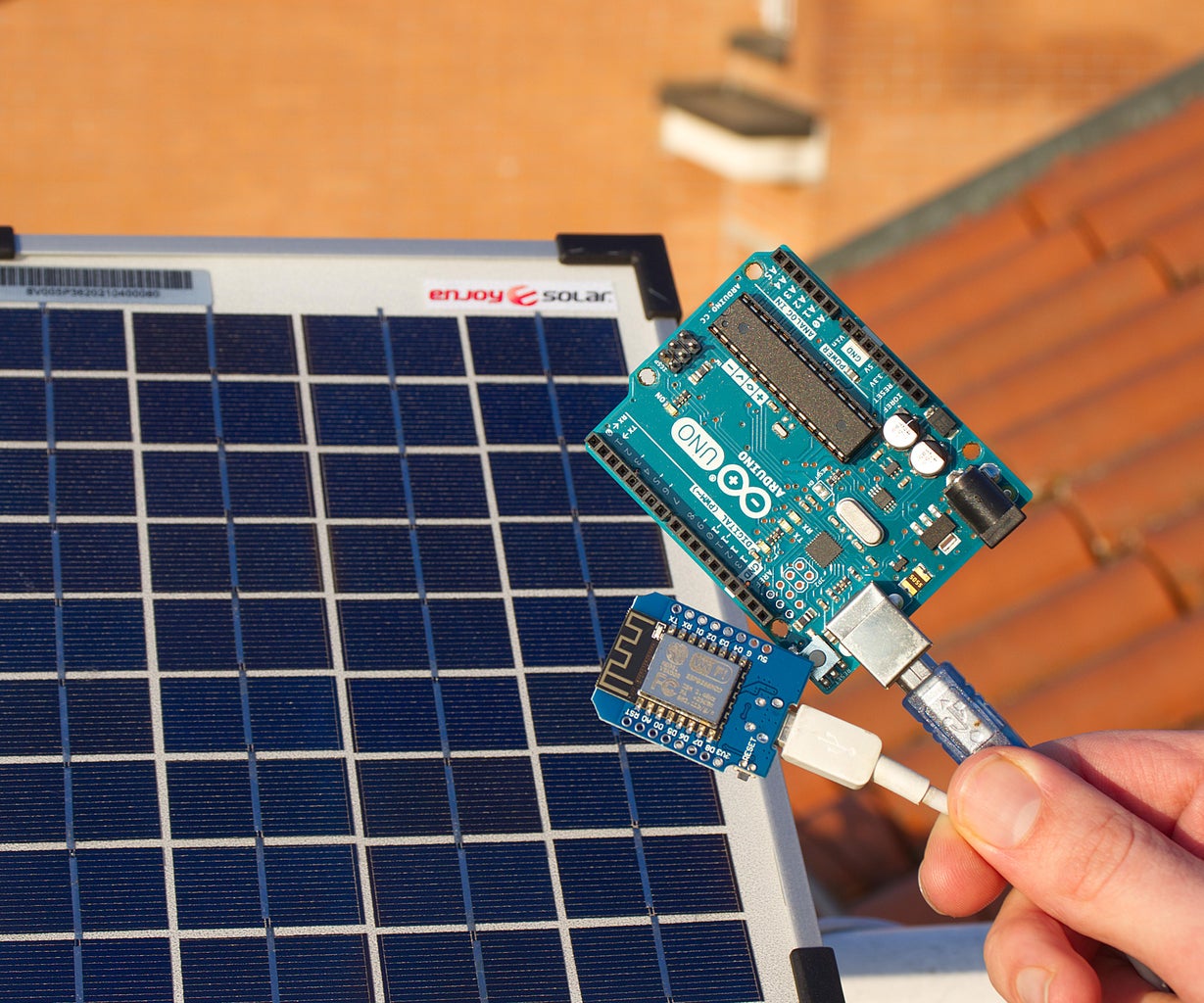


Hello and welcome to this Instructables guide. During these months I have been designing a system to automate my balcony vegetable garden. Connecting the various sensors put in the plants with wires would have been complicated and impractical. So today let's see how I built this small solar system that I will use to power an ESP32 board connected to a WiFi network and the various sensors for this project. This solar system is perfect for powering loads that consume very little power, such as an Arduino or an ESP32. So it is very useful for running electronics projects that need to be outside, such as weather stations, irrigation systems, and security sensors. A battery will be connected to the solar panel, to power the ESP32 even at night. But now, let's get started!
To see more details about this project, watch the video on my YouTube channel (it is in Italian but it has English subtitles).
Supplies


Electronic components for this project:
- Solar panel: in this case I will use an 18v, 5w one. I chose this panel because it has a glass cover, so it will last a very long time
- 3.7v lithium battery: i will use an 18650, but in theory LiPo batteries should also be fine. Always be careful with these batteries because they can explode or catch fire if a short circuit is made
- TP4056 board: this board uses the 5v input to charge the lithium battery with the right voltage and current, and it also has the function of preventing the battery from over-discharging
- Step-down voltage regulator: this is used to lower the voltage of the solar panel to 5v
- Step-up voltage regulator: this is used to bring the battery's voltage of about 3.7v to 5v, which is the voltage the ESP32 needs. For boards with the microcontroller running at 3.3v, we could directly bring the battery voltage to 3.3v, although this is a bit more complicated.
Other materials:
- Aluminium profile
- Bolts, washers and nuts
- Wires
- Pole to mount the solar panel (I used electrical conduit)
Tools:
- Soldering iron
- Drill
- 3D printer (optional)
Step 1: How the Circuit Works

Before we start building, let's see how the circuit works. The output of about 18v from the solar panel enters the voltage regulator, which is set to 5v. The output of the voltage regulator is connected to the input of TP4056, which charges the battery. Then, to the two pins for the battery is connected the 3.7v lithium battery. Now that leaves out the step-up voltage regulator that brings the battery voltage to 5v. This module will be connected to the output of the battery charging board, but not directly. I put an 1N5817 diode on the positive, to make the current go only from the battery to the voltage regulator, and not vice versa. Then with another diode I connected the output of the solar panel 5v regulator to the input of the step-up regulator. The diodes are used to power the load during the day directly from the solar panel, without going from the battery. At night, the current simply goes from the battery to the charging board and the step-up regulator, which powers the ESP32. During the day, when the sun shines on the solar panel, the current from the solar panel enters the TP4056 and charges the battery, and the output will be fed directly from the solar panel, because with the two diodes the higher voltage is "passed through". In fact, the voltage of the regulator, which is 5v, is higher than the 4.2v of the battery.
In the picture above you can find the schematics of the circuit I explained.
Step 2: Adjusting Charging Current

Now let's try to see if this circuit actually works. But first we have to solve a problem: the board that charges the battery has a charging current of 1 ampere, but the solar panel cannot supply such a high current. So to adjust this current to a lower value we have to change the R3 resistor on the circuit (note that the resistor code may change in your board, however if you look at the schematic it is the resistor that sets the charging current). I will put a 10k ohm resistor, to get a charging current of about 130 mA. Soldering on such small pins by hand is not easy, but I managed to solder the new resistor without doing too much damage.
Step 3: Building the Circuit


To mount the three electronic boards I will use a piece of plexiglass.
I mounted on the piece of plexiglass with double-sided tape the solar panel voltage regulator, the charging circuit and the regulator that makes the 5v from the battery voltage. To this board I removed the USB output port, because I will connect the ESP32 which I need to power directly with wires. Now comes the time to make the connections between the various components, following the diagram we saw earlier.
Step 4: Other Connections


After an hour or so of work, I finished all the connections. To connect the load to be powered, which will be the ESP32, I soldered this JST connector to the output of the voltage regulator. In addition to the two 5v power supply pins, I also brought the battery voltage and the solar panel voltage to the connector, so the ESP32 will be able to measure this data and send it to Home Assistant.
To mount the battery, I made a 3D printed battery holder, with two spring contacts inside salvaged from some old Christmas lights.
To connect the solar panel to the rest of the circuit, I connected two wires to the solar panel with two ring terminals. These wires go to the input of the voltage regulator to which the circuit that charges the battery is connected.
Step 5: Solar Panel Support


And so our circuit is finished, but to see if the battery charging works well we need to test it outside. First, however, I need to build a stand for the solar panel. To do this I will use an angled aluminum profile and some 3D printed pieces. I drilled some holes in the aluminum profile, to screw in this 3D printed piece and then to attach it to the holes in the solar panel. Between the solar panel and the aluminum profile I put 3D printed spacers. I screwed into the center piece a plastic conduit that will hold the panel up. And so we finished our support.
Below you can find the .stl files for 3D printing.
Solar panel holder
Attachments

Step 6: Testing the Circuit


As I told you before I designed this circuit to power an ESP32 board that will be outside, so to check that everything is working I connected to the circuit we have made an ESP32 that every 10 minutes measures the battery voltage and sends it via WiFi to Home Assistant. Now I will not explain the ESP32 and Home Assistant part because we will see it in a future guide. Anyway since the ESP32 consumes more power than an Arduino, I had to use the deep sleep function, which makes it stay on only as long as needed, so the battery doesn't discharge too much.
I left the solar panel outside for a week, and everything seems to be working fine. In the battery voltage graph we see that in the daytime the battery is charged by the solar panel, and at night when the ESP32 is powered only by the battery still the battery does not discharge too much.
Step 7: Finished!


So we have finished this project, and it seems to work fine. In the next month I will make the garden automation system based on an ESP32 that will be powered by this solar panel and battery. I hope you found this guide interesting and maybe useful. If you have any suggestion to make this circuit better, write it in the comments!
To see more details, watch the video on my YouTube channel (it is in Italian but it has English subtitles).


![Tim's Mechanical Spider Leg [LU9685-20CU]](https://content.instructables.com/FFB/5R4I/LVKZ6G6R/FFB5R4ILVKZ6G6R.png?auto=webp&crop=1.2%3A1&frame=1&width=306)


