

Introduction: Touch Keypad


Many projects require a small keypad.
Capacitive keypads:
- have no moving parts ;
- require fewer wires than the same number of push-buttons ;
- which means your code is simpler.
But unlike push-buttons, which can be custom-wired so that each button appears in the correct position, the pad-layout for capacitive keyboards is fixed.
This instructable explains how to make a custom HEX keypad using a TTP229 capacitive keyboard module and an Arduino UNO R3 microcontroller. [1]
The following techniques are explained:
- the necessary TTP229 keypad modifications
- how to interpret the manufacturer’s data sheets
- how to “talk” to the TTP229 keypad using an Arduino
- how to remap the keypad numbers 1..16.
Larger keyboards are possible by grouping a number of keypads together
The estimated cost of parts, excluding the TFT display, is $10. [2]
Images
- photo 1 (cover) shows the HEX keypad output. [2]
- photo 2 shows the original unmodified keypad.
- Photo 3 shows the modified keypad.
- photo 4 shows the keypad without the optional display.
- The video shows the keypad in operation.
Notes
[1]
The hexadecimal number system (HEX) comprises the alpha-numeric symbols 0..9 and A..F
[2]
The TFT display is optional as all keystrokes are sent to the Arduino “Serial Monitor”.
Construction details for the TFT display are given in my instructable https://www.instructables.com/id/Arduino-TFT-Graph...
Step 1: Parts List
The following parts were obtained from https://www.aliexpress.com/ :
- 1 only 4x4 Keyboard TTP229 Digital Touch Sensor Capacitive Touch Switch Module
- 1 only Arduino UNO R3 Development Board ATmega328P with Straight Pin Header
- 4 only Arduino male-female jumper wires
The following parts were obtained locally:
- 1 only piece of plastic for mounting the components
- 8 only M3 x 9mm threaded nylon spacers
- 14 only M3 x 5mm bolts
The estimated cost of parts, excluding the TFT display, is $10 [1]
Notes
[1]
The TFT display is optional as all keystrokes are sent to the Arduino “Serial Monitor”.
Construction details for the TFT display are given in my instructable https://www.instructables.com/id/Arduino-TFT-Graph...
Step 2: Circuit Diagram
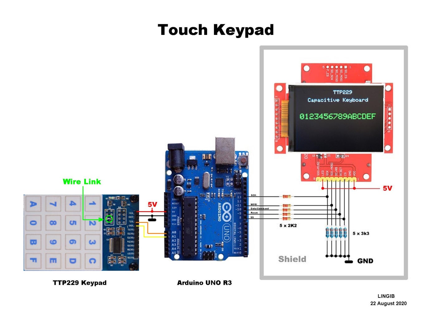
The circuit diagram is shown in photo 1.
A wire link (see diagram) is required to activate all keypads. Without this link only 8 of the 16 keypads will be active.
The keypad MUST be mounted on nylon spacers for reliable operation. If mounted too close to a surface the keypads think they have been pushed.
The keypad has two mounting holes at the top. I have placed two additional spacers at the opposite end to support the keypad when pressing down.
Step 3: Theory


This step contains technical information and may be ignored.
The TTP229 may be likened to to parallel-in serial-out shift-register. [1]
Negative (active-low) logic is being used.
Photo 1 shows the SDO (data) output when each of keys 1..8 are pressed in sequence.
- This sequence is not useful as keys 9..16 are inactive.
Photo 2 shows the SDO (data) output when TP2 (testpoint 2) is bridged with a wire link. Here we see that:
- all 16 keys are active
- there is only one zero in each of the keypad positions which makes decoding easy.
Photo 3 shows the TTP229 timing diagram. The timing diagram is read from left to right. Not immediately obvious is the fact that the SDO (data) line is bi-directional ... that is data flows both ways. The SCL (clock) line is shown above.
Photo 4 tables the mandatory durations for DV, Tw, and Tout.
Reading the keyboard
The Arduino code for extracting the data is shown below:
int scanKeys()
{
  // ----- locals
  int key = -1;                       // return value if key not pushed

  // ----- start scan
  digitalWrite(Data, LOW);            // active low start pulse
  delayMicroseconds(93);              // DV=93uS
  digitalWrite(Data, HIGH);
  delayMicroseconds(10);              // Tw=10uS

  // ----- listen for data
  pinMode(Data , INPUT);              // Arduino now listening

  // ----- shift keypad data out of chip
  for (int i = 1; i < 17; i++)        // scan 16 keypads
  {
    digitalWrite(Clock, LOW);         // F_SCL = 10^6/10 = 100KHz
    delayMicroseconds(5);             // 1/2 F_SCL period
    digitalWrite(Clock, HIGH);        // keypad data appears on rising clock-edge
    if (!digitalRead(Data)) key = i;  // record keypad number when data line goes low
    delayMicroseconds(5);             // 1/2 F_SCL period
  }
  delay(2);                           // Tout=2mS

  // ----- housekeeping
  pinMode(Data, OUTPUT);              // get ready for next key press
  digitalWrite(Data, HIGH);

  // ----- return data
  return key;                         // returns -1 if no key pressed
}
To start scanning we make the Arduino data line an OUTPUT then force it LOW for 93uS before raising it HIGH.
We then wait a further 10uS while the TTP229 reads the keypads.
At this point we program the Arduino data line to be an INPUT so that it can listen to what comes out of the TTP229 integrated circuit.
We then waggle the clock line 16 times to shift the data out. The data is valid each time the clock line goes from LOW to HIGH.
The simplest way to decode the keyboard is to count the number of waggles and record the count when a zero is detected.
Once the data has been shifted out we must wait a further 2mS for the chip to recover before asking it to scan the keypads once again.
According to the datasheet the clock frequency (F_CLK) can be anywhere between 1KHz and 512KHz.
I found the keyboard sensitivity increases with frequency ... 100Khz works well.
Response Time
Lets calculate the response time (T_resp) if we use a 100KHz (10uS) clock
- 93uS (DV)
- 10uS (Tw)
- 160uS (16 keys @ 10uS)
- 2000uS (Tout)
- ------------
- 2263uS
- 2.263mS (T_resp)
Reference
[1]
The Tontek TTP229 data sheet is available at https://www.tontek.com.tw/uploads/product/106/TTP2...
Step 4: Remapping Your Keyboard


The default output sequence from the TTP229 keyboard is:
- 1,2,3,4,5,6,7,8,9,10,11,12,13,14,15,16
But what if you need a HEX (hexadecimal) keyboard with the following output sequence:
- 0,1,2,3,4,5,6,7,8,9,A,B,C,D,E,F
The solution is to download the attached keyboard overlay and remap your keypad using a switch statement as shown in photo 1 and the code below:
void mapKeyboard(int key)
{
  switch (key) {
    case 1:
      Serial.println("1");
      tft.print("1");
      break;
    case 2:
      Serial.println("2");
      tft.print("2");
      break;
    case 3:
      Serial.println("3");
      tft.print("3");
      break;
    case 4:
      Serial.println("C");
      tft.print("C");
      break;
    case 5:
      Serial.println("4");
      tft.print("4");
      break;
    case 6:
      Serial.println("5");
      tft.print("5");
      break;
    case 7:
      Serial.println("6");
      tft.print("6");
      break;
    case 8:
      Serial.println("D");
      tft.print("D");
      break;
    case 9:
      Serial.println("7");
      tft.print("7");
      break;
    case 10:
      Serial.println("8");
      tft.print("8");
      break;
    case 11:
      Serial.println("9");
      tft.print("9");
      break;
    case 12:
      Serial.println("E");
      tft.print("E");
      break;
    case 13:
      Serial.println("A");
      tft.print("A");
      break;
    case 14:
      Serial.println("0");
      tft.print("0");
      break;
    case 15:
      Serial.println("B");
      tft.print("B");
      break;
    case 16:
      Serial.println("F");
      tft.print("F");
      break;
    default:
      break;
  }
}
A switch statement assigns a different code to each of the normal keypad outputs.
The output codes now match the attached keypad overlay.
Step 5: Software
Installation:
- Download the attached file “TTP229_keyboard,ino”
- Copy the contents to a new Arduino sketch
- Save the sketch as “TTP229_keyboard” without the .ino extension
- Upload the sketch to your Arduino.
- Open your “Serial Monitor” at 115200 bauds to run.
Attachments

Step 6: Summary
This instructable explains how to:
- configure a touch keyboard
- interpret the manufacturer’s data sheet
- write the necessary Arduino code
- remap (assign different codes to) each of the keys
A circuit diagram, sample code, and a keypad overlay are provided.
The estimated cost of parts, excluding the TFT display, is $10. [1]
Note
[1]
The TFT display is optional as all keystrokes are sent to the Arduino “Serial Monitor”.
Construction details for the TFT display are given in my instructable https://www.instructables.com/id/Arduino-TFT-Grap...
Click here to view my other instructables.

![Tim's Mechanical Spider Leg [LU9685-20CU]](https://content.instructables.com/FFB/5R4I/LVKZ6G6R/FFB5R4ILVKZ6G6R.png?auto=webp&crop=1.2%3A1&frame=1&width=306)


