

Introduction: Wireless Arduino Motor Driver and Joystick Controller (nRF24L01 and L293D)


I have designed an Arduino based wireless dual-motor driver board, it has an nRF24L01 transceiver module, dual L293D motor driver and an Arduino Nano V3 microcontroller. On the transmitter side, I built a breadboard Joystick controller, which also includes an nRF24L01 module. In this project, we wirelessly controlled a robot car chassis with two DC motors with a joystick. Let's take a look at the video on "how it works?".
Step 1: How It Works?
If you have viewed my previous projects, you may have noticed that I often use the nRF24L01 transceiver module. The nRF24L01 transceiver module is an easy-to-use low-cost wireless communication module. In this project, wireless communication was provided by using the nRF24L01 module on both the receiver and transmitter sides. Two L293D motor drivers were used on the receiver side and a two-axis joystick module was used on the transmitter side. Of course, there is an Arduino Nano V3 on both sides.
The analog values read from the X and Y axes of the joystick in the transmitter are processed by the Arduino Nano, and then the data is sent to the receiver via the nRF24L01 module. On the receiver side, the data received with the nRF24L01 are processed by the Arduino Nano, then the L293D motor drivers move the DC motors in the desired direction.
Step 2: Transceiver Communication Module


The nRF24L01 transceiver module allows two or more microcontroller to communicate with each other wirelessly and remotely. It also has the 2.4 GHz frequency band and the communication range is high enough. A transmitter and a receiver circuit are required to provide communication.
In this project, we built the receiver circuit as a motor driver, and a Joystick breadboard control circuit for the transmitter circuit.
An address (array of bytes) is created for two nRF24L01 modules to communicate. It communicates over this address and transfers data. If you are having any problem with getting it work, try adding a 10uF capacitor in parallel to the Vcc and Ground pins. Or you can use the power adapter module produced for the nRF24L01+
A popular library called RF24 is used to interface with the nRF24L01 transceiver module. RF24 Arduino Library for nRF24L01 Module: https://github.com/nRF24/RF24
Step 3: Two-Axis Joystick Module


Joystick module is mostly used in Arduino based DIY projects and Robot Control. The joystick module was used on the transmitter side of this project. It's very easy to connect and fun to use. The module gives analog output. We can use a Joystick Module with Arduino, Raspberry Pi and other Micro controllers. We just need to connect the VRx and VRy axis Pins to the Analog Pins of the microcontroller.
The output range is fixed for all directions. The image above shows the analog output value for the X and Y axis depending on the movement of the Joystick Module in four directions (+X, -X, +Y, -Y). You will also get some analog value as you move the knob diagonally.
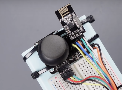
Step 4: The Joystick Transmitter Breadboard Circuit


We briefly mentioned the two basic components for the joystick transmitter hand controller. As seen in the circuit, a Joystick, an nRF24L01 transceiver and an Arduino Nano were used. Also, a powerbank was used for power. Make the connections according to the shared circuit diagram.
nRF24L01 to Arduino Nano Connections:
nRF24L01 VCC to (10uF) +5V
nRF24L01 GND to (10uF) GND
nRF24L01 CSN to Digital 9
nRF24L01 CE to Digital 10
nRF24L01 MOSI to Digital 11
nRF24L01 MISO to Digital 12
nRF24L01 SCK to Digital 13
Joystick to Arduino Nano Connections:
Joystick VCC to +5V
Joystick GND to GND
Joystick X to Analog 1
Joystick Y to Analog 2
I built the circuit on a 400 hole breadboard and fixed it on the powerbank. So I got a prototype that I could easily hold in my hand. You can also take a look and try the PCB version of Joystick Hand Controller, Accelerometer Hand Controller or Flexible Sensor Hand Controller from the links below.
https://www.instructables.com/The-Joystick-Hand-Controller-and-DIY-Camera-Slider/
https://www.instructables.com/The-Flexible-Sensor-Hand-Controller/
https://www.instructables.com/Hand-Gesture-Controller-for-Robotic/
Step 5: Motor Driver Receiver Breadboard Circuit
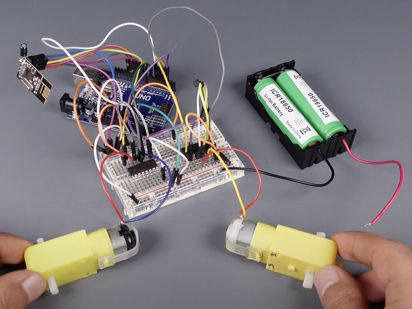


L293D IC motor drivers were used on the receiver side of the project. To briefly mention the L293D motor driver, one of the easiest and inexpensive way to control DC motors is to interface L293D Motor Driver IC with Arduino. It can control both speed and spinning direction of two DC motors.
Also, it can even control a unipolar stepper motor like 28BYJ-48 or Bipolar stepper motor like NEMA 17. The L293D is a dual-channel H-Bridge motor driver capable of driving a pair of DC motors or one stepper motor. That means it can individually drive up to two motors making it ideal for building two-wheel robot platforms.
The L293D motor driver IC actually has two power input pins viz. Vcc1 and Vcc2. Vcc1 is used for driving the internal logic circuitry which should be 5V
From Vcc2 pin the H-Bridge gets its power for driving the motors which can be 4.5Vto36V. And they both sink to a common ground named GND
The L293D motor driver’s output channels for the motor A and B are brought out to pins OUT1, OUT2 and OUT3, OUT4 respectively. You can connect two DC motors having voltages between 4.5 to 36V to these terminals.
Each channel on the IC can deliver up to 600mA to the DC motor. However, the amount of current supplied to the motor depends on system’s power supply.
Two DC motors can be controlled with one L293D IC motor driver, but the current supplied may be insufficient for more powerful DC motors. Therefore, two L293D ICs were used in the project, which also enables the use of two stepper motors.
You can connect the breadboard circuit according to the circuit diagram shared above. Two 3.7V 18650 Li-ion batteries were used for power.
Step 6: Motor Driver Printed Circuit Board


After building and testing the breadboard circuit, I designed a printed circuit board to turn the project into a useful prototype. Printed circuit boards are plates with conductive paths on the surface for mounting electronic circuit components.
To get the PCBs, simply upload the shared "Gerber file" from https://www.pcbway.com/project/shareproject/ to PCBWay and create an order. High-quality PCBs will arrive in a few days depending on the shipping address.
The Wireless Dual Motor Driver Board needs a few components. Easy solderable components. Place and solder components according to shared reference designator.
PCB dimensions are approximately 87mm x 51mm. Each motor has an input terminal for easy connection. There are also female headers for unused Arduino Nano pins. So you can include different sensors in your project.
Step 7: Transmitter and Receiver Source Code


Download the shared Receiver and Transmitter source codes. First of all, the first thing you need to do is download and install a popular library called RF24 to interface with the nRF24L01 transceiver module. You must use the library manager for this. If you want, download the library from the link below and add it from the library manager, or search for the name RF24 from the library manager and press the install button.
On the transmitter side, the pins to which the Joystick X and Y axes are connected are defined. Two variables are defined to read data from the joystick X and Y axes. A total of two data will be sent and received for the two axes.
In both source codes, the pin number to which the CE and CSN pins of the nRF24L01 are connected is defined. Also, a unique address (0xE8E8F0F0E1L) is defined to enable communication between Transmitter and Receiver.
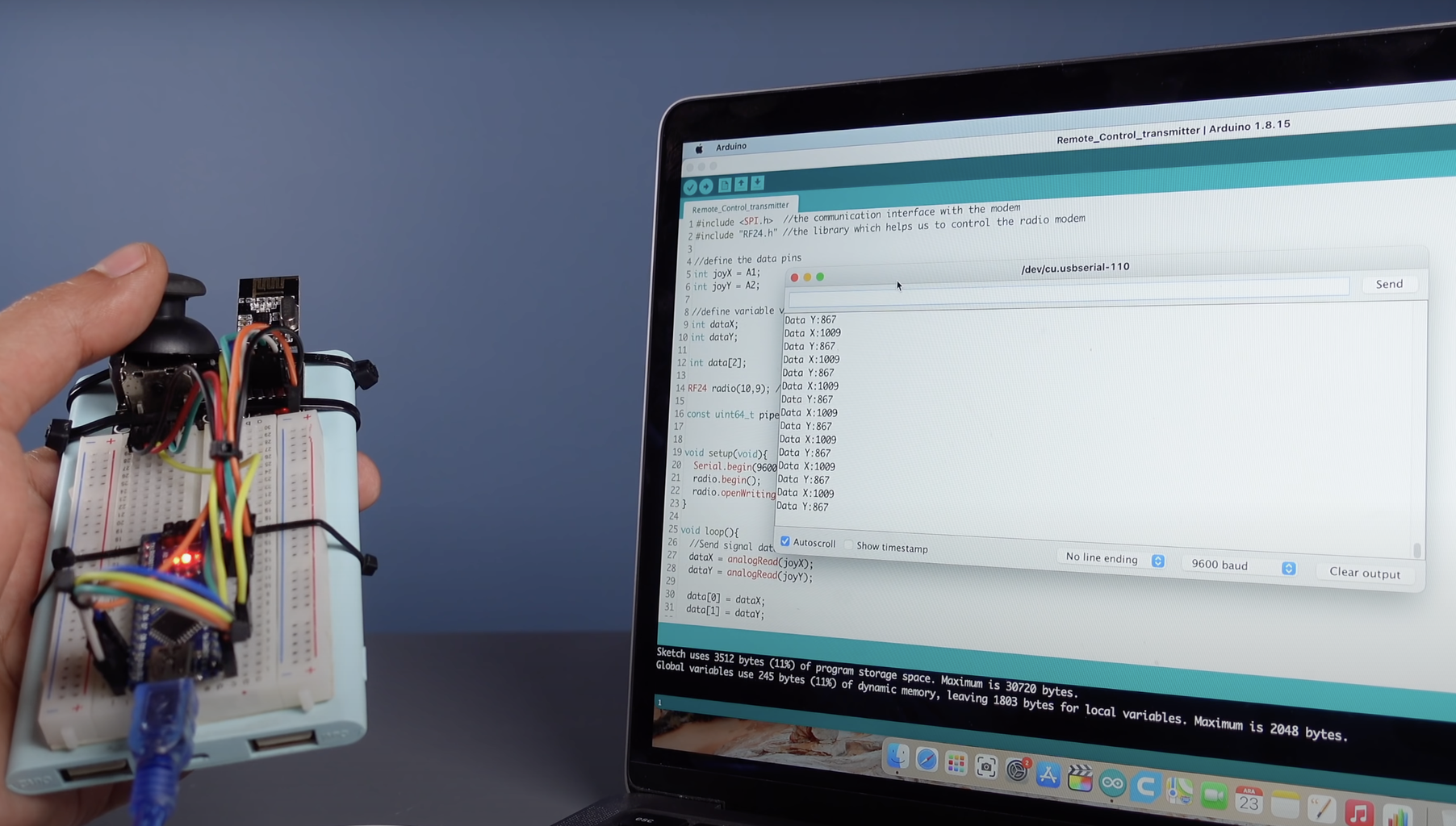
The analog values of the X and Y axes are read and a total of two data is sent. Then, by initiating serial communication, these two axis values are displayed on the serial monitor. View the displayed minimum - maximum values of the X and Y axes and note them for the Receiver side.
Open the Receiver source code, define the pins to which the motors are connected. Then enter the Transmitter X and Y axis values in the section of the motor control functions. Then upload the receiver code and display the transmitter/receiver communication on the serial monitor. For more details, please see the programming section of the project video.

Step 8: Assembly on the Robot Chassis


After editing and uploading the Receiver and Transmitter code, mount the motor driver board on a 2WD Robot Chassis of your choice, and connect the DC motors. If the motors move in opposite directions, change the positive and negative poles of the DC motors at the motor input terminal.
If you run into a problem please leave a comment, I will reply as soon as possible. Thanks for reading.


![Tim's Mechanical Spider Leg [LU9685-20CU]](https://content.instructables.com/FFB/5R4I/LVKZ6G6R/FFB5R4ILVKZ6G6R.png?auto=webp&crop=1.2%3A1&frame=1&width=306)


