

Introduction: Rocket Ship Panel


My most ambitious Instructable. This took me, part time a year to produce. I came across a quote that really described my ‘journey’ if you will – making this thing.
“I am always doing that which I cannot do, in order that I may learn how to do it.” ― Pablo Picasso
Step 1: Overview


When I set out to build it, I had no idea how I would do it, I had an idea in my head of what I wanted, that was it.
I had to learn new tools to use (co2 laser cutters and Coral Draw to name a few) as well as a tremendous amount of time figuring out how to make the panels. It also drained every bit of creativity out of me during the process coming up with themes for each of the panels.
My company happens to put on its own maker faire every year and I built this to show at that event. I have always been fascinated with switches and dials on control panels (what kid isn't), dashboards, space ships, aircraft cockpits and after checking out some other examples on the web I decided to put something together on my own.
Here is a link to a pinterest board I built while putting this together.
Step 2: Special Tools Used


40W CO2 Laser Cutter – the ‘eBay’ laser cutter
Corel Draw – Turns out the only way you are going to really be able to leverage the laser cutter is to use Corel Draw and an ‘add-in’ that can turn what you create on the screen send it to the laser cutter to cut. The free software that comes with it is completely useless – (you heard it from me)
Other tools used:
Just about everything you can think of, table saw, dremel, hand drills, drill press, etc. etc. etc.
Step 3: Parts


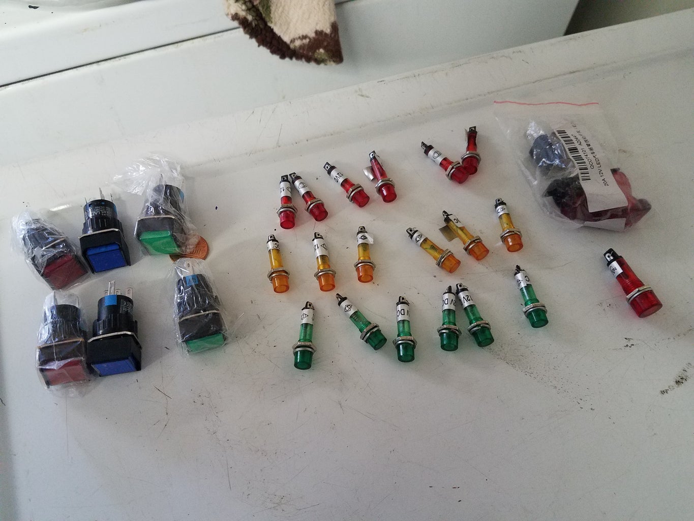


I found all of the parts on eBay, Amazon and AliExpress. When I started doing this I didn’t know exactly where it would go so I over ordered a lot of the switches, dials, lights, push buttons, LEDs in larger quantities that I would probably use . Since they were pretty inexpensive and given the time delay for AliExpress (weeks typically) I didn’t want to have to over pay for a single switch on Amazon that I could get in two days but would cost as much as a half dozen of the same thing from AliExpress.
On AliExpress, you have to really do your homework. A 12v light for example may be sold by dozens different vendors all with different prices. Also, know the different between SPDT, DPPT switches, momentary vs latched. Also lights will be in the same format and be for 12v,24v,120v,220v so read carefully.
Another thing about AliExpress, Amazon and eBay, I know a single vendor will sell their product in all three places because I see the same thing on all three with the same delivery times.
The video screen came from eBay and all of the Arduino’s and Pi’s came from Amazon. It has Three Arduinos and one pi in total.
Step 4: Design


So I had a grandiose cockpit that I wanted to build, wrap around, every switch or dial doing something. I kept that idea for a long time.
I also, originally wanted all the panels, fonts, colors to be consistent – like it was from the same ship/manufacture, same touch and feel. What happened over time is that looking at hundreds of example panels (my Pinterest board got pretty big) I decided there was so many different looks/colors, etc. that I would abandon that idea and make each unique – given the restraints of the tools I had and the switches, lights, etc. I had to work with.
After a time I decided to just make the individual panels and when I had enough of them figure out how to show them. Of course, time constraints hit home and it ended up being one large flat board.
I tried to make everything reference a particular science fiction movie that I liked when I was a kid.
CorelDraw & the Laser Cutter
When I purchased the laser cutter, it came with some free software. After toiling with it for a day or two I realized very quickly that the program wasn’t anywhere near what I needed. The cutter supported a software add-in that worked with CorelDraw. I had never used this program before, but I was kind of stuck. Fortunately, CorelDraw sells their software on a subscription basis. So I had to fork over the cost of renting the software for a year (vs completely purchasing it) otherwise my laser cutter was going nowhere – same as my project.
I use Rhino Cad and Photo shop but CorelDraw is its own animal. Not intuitive, but powerful, and very tedious to use. So along with everything else, I spent days and days learning how to create what I’m showing in this instructable. In addition, using it with the laser cutter is another project in itself. I went through a lot of wasted samples figuring out making the two dance together. In the end, I worked out a process that worked for me.
Step 5: Making the Panels


This was by far the most difficult part. A tremendous amount of time was spent just figuring out HOW to make them, let alone doing the artwork for it or wiring it.
So, distilled down here is the process I used to make a panel
* Have a rough idea of what I want to make – reference picture, drawing on a napkin, etc.
* Identify all of the switches/lights/knobs, etc. that will be used on the panel.
* Draw the panel in CorelDraw. Multiple layers are used in each one – one layer is used for the cutting of the panel with the laser cutter, the other is for the actual print out.
* After days/hours/weeks of drawing/re-drawing the panel, prepare to make it.
* For the backing I used 3/16 MDF. I went through about a ½ dozen types of MDF trying to find one that would cut easily on the laser cutter and not have to run it at 100% power or make two passes on cutting it.
* So, I would cut the panel, verify that the hole sizes fit all of the switches and lights.
* Print out the panel itself. I tried a number of different photo paper to find one that I liked. I found out very quickly that the printed picture of the panel would smudge easily, so I needed to add a clear covering on top of it. That – was a challenge in itself figuring out how to roll on the clear perfectly, no creases or air bubbles. I wasted a LOT of printouts and clear covering material working through this.
* So now, you have a piece of MDF and a print out of your panel that is covered in a protective clear sheet. Now you have to glue the sheet to the MDF. This again, took many, many trial and errors before I worked up a technique that would work. This is important because you can’t afford to have any mis-alignment or the holes in the MDF aren’t gonna line up with the printed text. I used a 3m sticky spray for this – very sticky stuff. Once it gets a hold of both of them, it will tear the paper trying to pull it apart – even if it is stuck only for a second so a steady hand is necessary.
* Cutting the holes in the paper to match the MDF. This as it turns out wasn’t so hard. With the photo paper mated to the clear protective it makes for a pretty strong piece of paper. I carefully cut the holes with a super sharp Xacto knife from behind. For the mounting holes at the four corners of the panel I used a leather hole puncher that worked really well. I actually punched the holes on the paper before I glued it to the MDF. This allowed me to align the paper to the MDF when gluing the two together.
All of the lights that mount in the panel are wider for the light than the rest of itself – so it doesn’t fall through the hole. When I would cut the holes, they weren’t perfect but any extra would typically be covered over when the light was pushed in. Even the switches and buttons have a nut and lock washer that will compensate if the hole isn’t perfectly cut.
Now the panel is ready to be used – put the controls put in and initial wiring. Rinse and repeat for the rest of the panels…
Step 6: CPU Panel


This was the first one I attempted and the most primitive. This is loosely based on a Burroughs B205 that showed up in a lot of campy 60s and 70s shows. Batman, Lost in Space and Time Tunnel to name a few.
I hand drilled the holes for the marbles and using plastic tubing and Christmas lights put this thing to together. All with RTV/Silicon sealer/glue – what a mess. And the wiring was even more difficult and messy.
As it turns out a Christmas light bulb is 3.3v – NOT 120v. So to drive them I use an Arduino driving a 4-relay board that switches the lights off and on. I had to purchase two separate 3.3v power supplies to drive this – I believe it’s using about 8AMPS to power those lights. They used so much current I can’t light all of them at once! When I do, the power supplies shut off – current overload or something. The lights were wired up in parallel in a random order so that when each relay is pulled in a random pattern of lights is lit.
After completing this, I knew drilling the holes on a panel by hand wasn’t going to work. Also using incandescent bulbs should be avoided when possible because with as many as I was planning to use I was going to need a lot of power supplies to drive it.
Step 7: Monitor


The monitor is driven by a Pi running a small python script that spawns and kills omxplayer programs. I ended up using 13 gpio lines for rotary switches on the panel that so each time a knob is turned the pi catches the change, kills the current omxplayer, and starts a new one. Omxplayer is an amazing program. It allows for so much fine grain adjustment of things, rotating the image, etc.
For the movies, I literally sat my phone up on a little tripod and recorded bits of movies off of YouTube, saved them in the correct format that Pi can use and uploaded them to the pi on a usb.
The monitor is a 9 inch TFT LCD Display Module HDMI+VGA+2AV Driver Board for Raspberry Pi they are all over eBay for purchase. The monitor only needs 12v to run which is nice.
For mounting, I did more drawings in CorelDraw and cut the frame and box that the monitor is mounted in.
For the speaker. I found a simple design l liked and drew it up in CoralDraw and laser cut it. I'm using a Adafruit amplifer do drive the sound from the pi into the speaker.
Step 8: Infinity Mirror


I wanted to try my hand on making an infinity mirror and I had some success with this one. If I make a new one, I will definitely do things differently. For the LEDs, I used Adafruit’s Neopixel addressable leds. I leveraged their libraries to get my sample code running on a Arduino in minutes.
I had originally wanted each knob to do something different with the lights but again with the time crunch I ended up just using two knobs.
Another thing I would have changed is to make the mirror deeper so that the leds would end up at a single point. Again, live and learn.
For the mounting, more drawings in CorelDraw and laser cut.
LEDs
Step 9: The Rest of the Panels


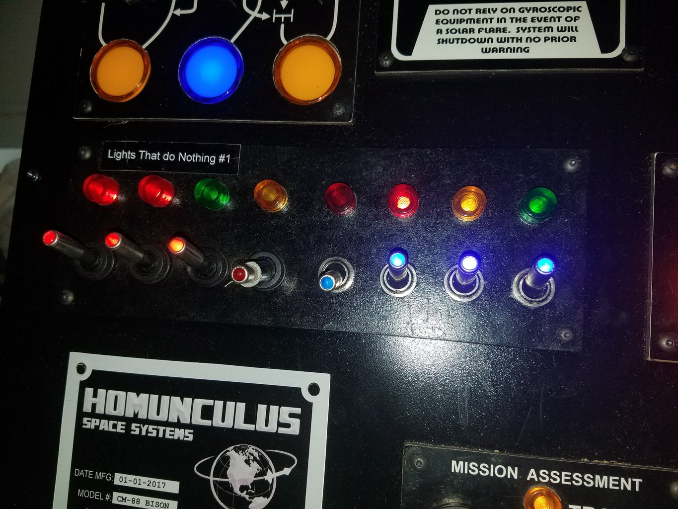

A couple of the panels do nothing – I just ran out of time and ideas about what they could do. Others are basic flick a switch, a light comes on.
Step 10: Mounting the Panels to the Larger Panel


So I did some fooling around with how the panels should be placed, what looks best, etc. I figured out how big the mounting piece that all the panels needed to be. Then I went out and purchased a piece of aluminum for the job. I had to be very careful here because it was going to be a ton of work to make all these cuts and aesthetically I didn’t want extra holes or patching over things when I mess up. Measure twice, cut once.
So I printed out all of the panels on plain paper, cut them out and taped them to the aluminum sheet. From there, I used a center punch to mark all of the mounting hole in the corners of the panels. For the rest, I just figured out how best to make cuts that would allow the panel to fit.
I used a dremel with a cut off wheel. During the process, I bent/broke so many of the shafts I ended up buying all the spares at all the hardware stores in my area. I had to end up going on amazon and buying more. A super tiny screw holds the cutoff wheel to the shaft. It doesn’t take much for it to snap off.
So with a lot of patience and measuring twice and cutting once I had the master panel cut.
For the box itself, some MDF, circular saw and table saw, sheet rock screws and some gluing, and it was together.
Step 11: Wiring


Are we having fun yet...
Lots and lots of soldering, I worked out the details as I went. Smaller diameter wires are better than bigger diameter wires - when you are working through a spiderweb of them. I used connection blocks for + and - rather than chain things across multiple panels. Easier for trouble shooting.
This isn’t a good example of wiring. It was very much a get-er-done approach. The event was a few weeks away and except for the infinity mirror and CPU panel none of the code was written for the other Arduinos or the pi and none of the wiring was done. I had to keep adding 12v power supplies to the project because there were so many incandescent lights. My speed soldering skills have very much improved since completing this.
Step 12: Movie References
I figured I'll just add this here. All of the references from the movies the project used.
Star Wars
Star Wars the Empire Strikes back
5th Element
The Jack Benny Show (creepy smoking guy)
Moon
Alien
Aliens
Batman/Lost In Space/Time Tunnel
The Adventures of Buckaroo Banzai Across the 8th Dimension
Dr Strangelove
Darkstar
Star Trek
Agents of Shield

Runner Up in the
LED Contest 2017

Participated in the
Raspberry Pi Contest 2017

Participated in the
Wireless Contest

Participated in the
Design For Kids Challenge


