

Introduction: Arduino/App Controlled Desk Light


For this project I wanted something that would allow me to teach myself more about electronics/software , something I've not really gotten into yet.. I decided a light would be a good platform for this.
The design I came up with was for an uplighter which features colour and brightness adjustment. On product, the warm to cool white colour temperature and brightness is controlled via the 'puck', its position and orientation changing these independently - quite a unique/fun interaction.

I also ended up creating an App (might as well challenge myself) to adjust these, as well as adding additional functionality to control some RGB LED's and set a sunrise alarm. The sunrise alarm gradually increases the brightness over 30mins to help you wake up.
As this is my first Arduino/App project I'm assuming there will definitely be better ways of doing the code so go easy on me! It worlks, so I'm happy. If you have suggestions on improvements etc would be good to hear..
All the files for this project (arduino/app inventor code, app graphics etc) and the App apk. can be found at this link.
I've entered this into the Raspberry Pi and FULL SPECTRUM LASER contests, so if you think its worthy a vote would be massively appreciated!!
What you need....
Elec. Components:
- Arduino Micro
- 12 Linear Radiometric Hall Effect Sensors
- DC Jack
- 12V Power Supply
- 2x 1W Cool White LED's (6000K)
- 2x 1W Warm White LED's (2800K)
- 4x Adafruit RGB Neopixels
- Sparkfun Picobuck 350mA constant current driver
- HC06 Bluetooth module
- Prototype board
- Terminal blocks
- Wires
Materials:
- Mold making materials (cardboard or silicone etc)
- Polyurethane Casting Resin
- Plywood
Consumables:
- Solder
- Spray paint
- Sandpaper
- Mixing cups/stirrers
Tools:
- Soldering Iron
- Glue gun
- Pliers/screwdrivers/knifes etc.
- Laser Cutter
Software:
- Arduino
- MIT App Inventor (free web based)
- Photoshop or something to create App graphics
Step 1: Hall Effect Sensors
For the product control/interaction I was looking to come up with something a little different, not just a dial or something.
After a bit of research into different types of electronic components, I found linear radiometric hall effect sensors. These are basically a sensor that's output is affected by magnetic fields. Usually the sensors output is half the input voltage. However when a magnet is brought near it, the output will either rise to the input voltage or fall to 0V (saturation limits) depending on whether its the north or south pole of the magnet.

I realised I could utilise this to allow me to control two different settings on a single hall sensor - the 'puck' idea was born. A magnet is hidden in the laser cut puck and would control either brightness or colour temp depending on which end was facing the sensors. I go into the Arduino code later, but essentially I read these sensors and look for whether the output has risen above a 'high trigger' or fallen below the 'low trigger'. I use multiple hall effect sensors to allow me to map a specific colour temp and brightness value onto each, which get triggered as you slide the puck around the arc..

Step 2: Electronics Hardware


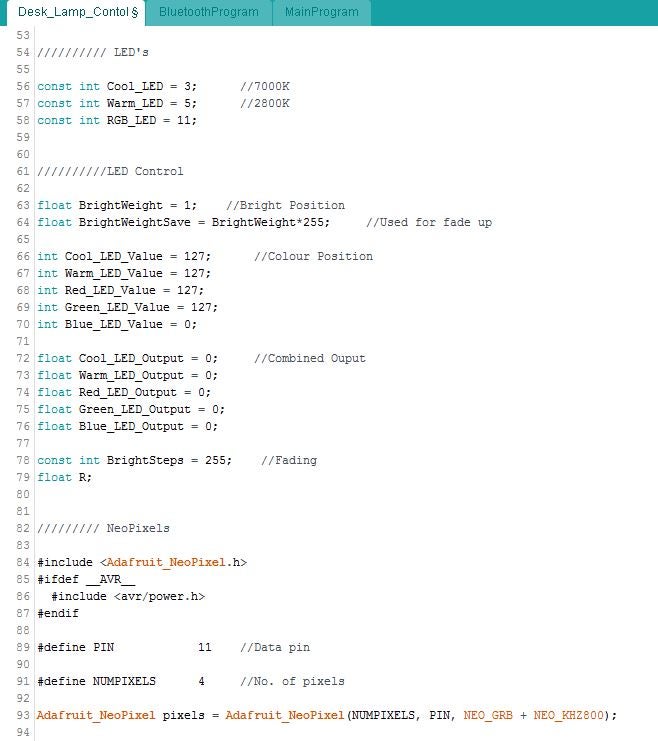
The first step of this project was to connect up the electronics hardware. I chose to use an Arduino Micro as it has a good number of analog read pins - allowing me to use multiple hall effect sensors to give enough resolution for the setting adjustment. A 12V DC power supply is split between powering the Arduino and LED driver.
The control arc uses 11 hall sensors, with another 1 used to turn the light off. These were connected into pins A0->A5 and 4,6,8,9,10,12. They share a common 5v and ground rail/pin.
The LED's I used are 1W and require a constant current driver. The Sparkfun PicoBuck was used as it delivers a constant 350mA to up to 3 output channels. The 12V supply is connected into the drivers Vin pins. The driver has input pins to control the PWM of the outputs, these were connected to pins 3 and 5 of the Arduino.
The bluetooth module was then connected. Bluetooth Rx-> Arduino Tx, Tx-> Rx and 5v.ground.

The LED's were mounted on a separate board. Two cool white LED's are connected in series, as are the warm ones. These connect into Output 1 and 2 of the driver. The RGB LED's are Adafruit Neopixels; these are chainable modules that you can control the colour and brightness of individually from one Arduino pin. These connect into pin 11 and the 5V/ground pins.
Step 3: App Inventor


To create the App I used MIT App Inventor, its free and pretty easy to learn/use. I first had to create the App screens/graphics - this can be done in photoshop etc. It makes it easier in App Inventor if you have all the components that make up the screens as separate images/files.
App Inventor has two views, theres the 'Designer' tab for the front end visual stuff and the 'Blocks' tab for the code.
Using the 'Designer' tab I built up the app screens. One issue I found is that the bluetooth component doesn't work across multiple screens so after the 'welcome' screen all the others (connection,RGB,colour temp,alarm) are all created in the same screen - effectively layers that I turn on/off.
The main tools I used are for 'layout/alignment' and 'canvas'. A canvas is a touch sensitive area that you can show as an image.
Once the visuals are setup, its time to switch to the 'Blocks' tab and write the code. I'll describe it in brief, buts its probably easier if you import my file into App Inventor and have a play around yourself...
These first blocks are for the connection screens. To allow the App to try automatically connecting to the Arduinos bluetooth module I create and set a variable to the address of my HC06. I use a timer to change the background image whilst it is connecting. If connection is successful then it loads up the colour temp screen. If the bluetooth fails to automatically connect, you need to press the 'connect to device' button. This will bring up a list of all the bluetooth devices your phone can see. The 'bluetoothclient1.connect' command uses the device address you select from that list to connect with.


These blocks control what happens when you touch each of the menu buttons - change between RGB, colour temp and alarm. As they're touched the applicable visual layers are turned on and off. I.e when you tap the RGB menu button it switches the background image of the buttons canvas to the dark icon, turns on the RGB screen and the other off.
The power and brightness control is shared between the RGB and colour temp screens. In order for the Arduino to know which LED's to control, I need to tell it which screen is loaded. A text string in the format (screen)? is sent by your phones bluetooth using command BluetoothClient1.SendText.
This block sends the string (Power)? whenever the power button is tapped.

These blocks control the colour temperature adjustment. When you touch the canvas, the Y coordinate of your touch point is used to set the variable 'cool'. The Y value is driven by the pixel size of the canvas, so in my case a value between 0 and 450. I use the multiplier to convert that into a usable PWM value (0-255). I then send a string with that value and an identifier in the form (Tempvalue)?.

Similar blocks as above but for the brightness control. Using the X coordinate this time and different multipliers to set the variable 'Bright' to a value between 10 and 100.

These blocks are for the RGB control. There is a command called 'GetPixelColor' that can be used to get an RGB value of pixel your finger is touching. It outputs the value with an extra 255 at the end for some reason, so I do a bit of work to get the value into the format (RGBredvalue.greenvalue.bluevalue.)? Again this is then sent to the Arduino, but with RGB as an identifier in the string.

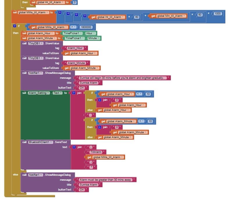
The next section of blocks is for the alarm settings. The first block controls what happens when you touch/drag the sun up and down. Again, the 'get current X and Y' commands are used to get a value for where your finger is and change the background image depending on the height of the sun. The suns position also drivers whether the alarm is enabled or disabled, this is send by bluetooth.

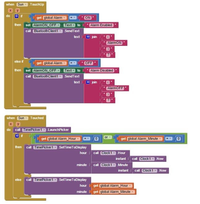
When you tap or finish moving the sun it brings up the time picker to allow you to set an alarm time. The main part of this next block is using the current time to work out how many milliseconds there are until alarm setting. This value is then sent to the Arduino

In the next step I cover how the Arduino reads and uses the strings...
Step 4: Arduino Code
As with the App code i'll cover this briefly....
First I setup all my variables, assigning the sensors and LED's to the correct pins. The output from the hall effect sensors will be read using the analogRead function, giving a value between 0 and 1023. As previously described it outputs half when no magnets present, so around 500. I use Low and High trigger variables to allow me to easily adjust when it knows the puck is over the sensor.

The neopixels require a library so thats defined here..

The void setup starts the serials, for the Micro the Rx/Tx pins (bluetooth) use Serial1.. The pins are then set to be inputs or outputs and LED's set to off.

Now its the main loop...
This first section is checking whether any data is being received from the App. Serial1.available() is reading the serial and getting the number of bytes in the string. If thats >0 I know datas incoming.
If you remember, all strings that I send from the App end with a question mark.... i.e (Bright100)?
I use the function .readStringUntil to read the serial data up to the question mark (Bright100) and set the variable BTstring to this. I check whether BTstring ends with a ')' to make sure complete commands are being received. If they are, then the BluetoothProgram loop is callled... this is described further down..

This next bit controls the sunrise alarm. Basically if the alarm is enabled and the time is correct then it will start fading up the LED's. Due to the human eye perceiving light logarithmically is better to do any kind of LED fade ups/down with a exponential curve rather than linear. Hence an equation is driving the PWM values...

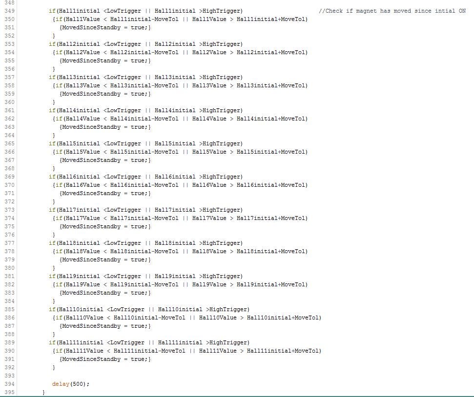
To avoid the puck interfering with App control it gets deactivated when you use the App. To re-activate the puck you need to move it off the product for 5 seconds.. This bit of code first checks whether all the sensors are outputting a steady state value (no magnet) and then starts a timer. When 5 seconds is complete the BTinControl variable is set back to false.

The code for the puck now.. First the sensors need to be read.
If the light is currently off, it will check whether any of the sensors are above or below the trigger points i.e the puck has been placed on the arc. If it is then it will fade up the white LED's to your last setting no matter where you place it.


To keep the LED's set to your last setting instead of updating to the values associated with whatever sensors its triggering, the MovedSinceStandby variable is set to false. This next bit of code basically checks whether you've moved the puck from its initial position by a set amount....

If you are moving the puck the 'MainProgram' is called to update the brightness/colour temp. This is described further down.

The last bit in this main loop checks whether the puck has been placed back on the standby dock - is sensor 12 reading a value above/below a trigger point. If so it fades the LED back down..

The bluetooth loop:
As described above when data is received via bluetooth, the string is read. We now need to check what that string says...
All strings apart from brightness, colour temp and RGB are quite easy to deal with. You check whether BTstring is equal to the text sent from the App.
If you recall, whenever you change screens in the App it will send a bluetooth command. Here we question for that and set some variables to true or false so we know which screen you're on.
Notice at the end of each section I set the BTinControl variable to true and clear the BTstring value.


When you tap the power button in the App it will fade the LEDs up or down. The variables set above for which screen you're on are used to decide whether its the RGB or white LED's to control..


For brightness, colour temp and RGB I need to read the strings in a slightly different way. Because the number part of the string will be changing I question whether the string starts with one of the identifiers not the full string, so just (Bright here..
I now need to separate out the actual brightness value from the string. The format of the string sent from the App is (Brightvalue) so I therefore know the brightness value will be between the 't' and the ')'. The position of the 't' will remain constant, it will always be the 7th character in the string. But because the brightness value can be between 10 and 100 the position of the ')' will change. I use the .indexOf command to work out where the ')' is, what character it is and can then use the .substring command to read the string between the 7th character and the ')' character position. This leaves me with just the brightness value which I can use to adjust the RGB or white LED's depending on screen.

Colour temp adjustment is a similar process to above but the value will be between the 'p' and the ')' this time...

For the RGB adjustment we have three values to extract from the string, but its a similar process again. From the app we receive strings in the form (RGBvalue.value.value)
So I know the red value will be between the 'B' and the first full stop. The green value is between the 1st/2nd full stops and the blue value is between the 2nd full stop and the ')'.
Once we have the values the neopixles are set to the new colour...

Here we check whether the alarm is being enabled or disabled. If the alarm time is changed we will get sent a string with the number of milliseconds from now till the alarm. Again this value is extracted from the string and in order to be able to check whether its time to start the sunrise we need to set a variable to the current time (millis)..

Puck controls:
As described before if the puck (magnet) is one way up it will drive the hall sensor output below the low trigger and if the other way up above the high trigger.
This allows control of both brightness and colour temp on the same arc..
The sensors values are read. If any of them are less than the low trigger value then we are adjusting colour temp. There are 11 sensors under the arc area, which outputs will in turn go below the trigger point as the puck is move over them. Each sensor has a PWM value for the cool and warm LEDs against it, starting with sensor 1 at 100% warm, 0% cool and working to the 11th at 0% warm, 100% cool.


The brightness control is done in the same way.. checking if the sensors outputs are above the high trigger this time and giving each sensor a brightness weighting value.
This brightness weighting is then multiplied with the colour temp value to give the overall output value. Allowing you to set any colour temp to any brightness...


Step 5: Housing


- I started by making a mold out of cardboard for the lower part of the housing. To create the recesses for the control area I had a piece of plywood laser cut into the arc shape and used a 5p coin for the 'standby' dock. These were glued down to the cardboard mold, paying attention to get them in the correct position that would align with the hall effect sensors.
- Next was to mix up the polyurethane resin. The stuff I use has a simple 1:1 ratio and cures within about 20mins.. so need to work fairly quickly!
- The initial pour was to fill the bottom of the mold. After this set I added an inner wall of cardboard to allow me to pour the side walls.
- To create the upper section, that the LED's would sit in, I cut and glued some plastic tube/cup in place at an angle. And again the resin was poured in and allowed to set.
- Now the housing was all set, I needed to drill out some holes and give it a good sand down.
- Primer was applied and then sprayed with the final top coat of paint.
Step 6: Assembly/Conclusion


- A slot for the DC jack was cut out of the housing. The jack is then glued in.
- The LED board can then be screwed down in the upper section, with the wires fed through to the lower part.
- The wires from the LED's and DC jack were then screwed into the correct terminal blocks.
- The main board is then screwed down into the housing
- A piece of plywood is then screwed down to cover up the bottom of the housing.
- The final thing is to glue the 'puck' together, making sure to orientate the poles of the magnet with the correct 'brightness' or 'colour temp' end cap.
Overall the light works pretty well! There's a few bugs in the software to iron out and the RGB LED's could be brighter. I may also add an ambient light sensor to automatically change the colour temperature, starting 'cool' during the day and changing into 'warm' at night.
Cheers for reading!
Participated in the
Raspberry Pi Contest 2016

Participated in the
Full Spectrum Laser Contest 2016


