

Introduction: Bookend Lamp - LED - USB - 3D Printed


This object fulfills two tasks at a time. On the one hand it is a bookend and on the other it brings light between the books, a kind o a kind of ambient light on the bookshelf.
The light source consists of LED strips (warm white) that receive their power (5W) via a USB power supply unit.
Dimensions: Height: 150 mm Length 165 Width 150 mm
Supplies
- 3D printer
- filament(s) (PLA or PETg)
- self-tapping screws Ø 2 x 5mm (2x)
- screws Ø m3 x 5 mm plus matching nuts (2x)
- 125x32mm polycarbonate twin-wall sheet, thickness 6mm (or transparent polycarbonate glass, 3mm thick)
- tinplate 125x35x1mm (alternative to the LED strip mounting plate)
- Philips screw driver
- fretsaw (metal blade)
- scissors
- glue
Especially for the light installation you need:
- approx. 50 cm LED strip
- two position Mini Toggle Switch
- switch wire, approx. 80 cm (preferably 2 different cable colors)
- 2-pole cable with USB plug (length depends on the local power connection options)
- USB power supply unit
- soldering iron (with thin soldering tip, because of the soldering on the LED strips)
- solder
- soldering grease
- cable stripper
- shrink tubing
- cable tie


Step 1: Printing Parts


Parts to print:
- "Bookend lamp_lampshade.stl"
- "Bookend lamp_lampshade top.stl"
- "Bookend lamp_LED strips mounting plate.stl"
- "Bookend lamp_bookend.stl"
I started by printing "Bookend lamp_lampshade.stl " and "Bookend lamp_lampshade top.stl". This allowed me to start the time-consuming work of installing the LED strips and soldering them while "Bookend lamp_lampschade.stl" was being printed. This took about 8 hours.
Print settings:
- Printer brand Prusa
- Printer: I3 MK3S
- Supports: No
- Resolution: 0,2
- Infill: 10%
- Filament brand: Prusa; ICE
- Filament color: Galaxy Black; Wintershine White
- Filament material: PLA
Remark: As all parts are designed to fit very precisely, it may happen that you have to rework one or the other part a bit with sandpaper and/or cutter due to different dimensional accuracy of the printers and the different behavior of the filaments.
Step 2: Sawing Plate for LED Strips


After all the parts have been printed, you could start installing the LED strips.
I recommend a tinplate plate as it absorbs the slight heat generated by the LEDs better than a PLA plate. I still had some leftover stock. But I don't think it's necessary to buy a larger tinplate plate from a DIY store just for this reason.
However, another argument in favor of a tin plate is that the LED strips stick better to tin than to PLA.
Using a fretsaw with a metal blade, I cut a 32 x 125 mm tin plate to size.
Note: If you don't want to use a sheet metal plate but "Bookend lamp_LED strips mounting plate.stl" (last picture) instead, you can save yourself this step.
Step 3: Sawing "glas" to Size


For this work step you need:
- polycarbonate twin-wall sheet, thickness 6 mm (I'll call it "glass" from now on)
- fretsaw with very fine saw blade
- fineliner or piercer
- glue
There is hardly anyone who will have a polycarbonate twin-wall sheet in stock at home, and no one is likely to buy a whole 1m x 2m sheet just for a few square centimeters. Perhaps there are similar plates in smaller sizes. Otherwise I recommend polycarbonate glass 3mm thick, 70% translucency or transparent polycarbonate glass. These are available in our DIY stores in small sizes.
To cut the polycarbonate „glass“ exactly for this lampshade, put the top of "Bookend lamp_lampshade top.stl" on the "glass" and pull along the outside with a thin felt-tip pen or a pricker. The lampshade top should not slip in this process.
The „glass“ insert measures 125 x 35 mm. In my case the insert sits so tightly after insertion that the use of glue is not necessary. A small step ensures that the „glass“ - when inserting - cannot slip out of the lampshade downwards.
If the "glass" is too loose, you can fix from the inside (in the corners) with some glue.
Step 4: Cutting LED Strips to Size


Now you need
- approx. 50 cm of LED strip.
- scissors
We need 4 strips. Each strip consists of 7 LEDs.
Cut them with scissors exactly at the cutting lines.
Step 5: Attach LED Strips


For this step you need:
- the tin plate (or "Bookend lamp_LED strips mounting plate.stl")
- 4 LED strips with 7 LEDs
- "Bookend lamp_lampshade top.stl"
- self-tapping screws Ø 2 x 5mm (2x)
- Philips screw driver
- drill Ø 2,5mm
The installation surface must be smooth, clean and dry.
Tape the strips to the panel in such a way that a small center line remains free for the mounting holes. It is indeed very tight, so the LED strips should be as close to the outer edge of the plate as possible.
If a tinplate is used, holes must now be drilled to attach it to "Bookend lamp_lampshade top.stl".
This step is not necessary when using the PLA plate. The holes are already in place here.
For testing purposes, I screwed the LED plate to the "Bookend lamp_lampshade top.stl" cover.
I removed the LED plate again for the soldering process.
Step 6: Reconnecting LED Strips


The LED strips previously separated with the scissors must now be reconnected. Positive pole to positive pole and negative pole to negative pole (see pictures).
For this you need
- switch wire, preferably 2 different cable colors
- soldering iron (with thin soldering tip, because of the soldering on the LED strips)
- solder
- soldering grease
- cable stripper
It is a good idea to "place" a small drop of solder on the soldering points of the LED strip before soldering the cable. The small cable pieces should also be pre-formed before soldering. Dipping the free cable ends in soldering grease improves the flowability of the solder.
The first two pieces of cable should be at least 5 cm long. This is important for later wiring and assembly.
As soon as the poles of the first two strips are reconnected, use a battery to check whether the soldering has been carried out correctly. This check should also be carried out at the end of the LED strip assembly.
Note: If you have attached the LED strips to a sheet metal plate, you must ensure that no bare piece of cable touches the plate!
Now you can attach the finished LED plate again to "Bookend lamp_lampshade top.stl" with the two self-tapping screws Ø 2 x 5mm.
Step 7: Wiring (1) - Mounting Lampshade


Now you should have the following things ready
- the hopefully finalized "Bookend lamp_bookend.stl"
- "Bookend lamp_lampshade.stl"
- the fully assembled light unit
- screws Ø m3 x 5 mm plus matching nuts (2x)
- self-tapping screws Ø 2 x 5mm (2x)
- switch wire, approx. 40 cm (preferably 2 different cable colors)
- solder
- soldering grease
- cable stripper
- Philips screw driver
One particular difficulty is feeding cables from the base area up to the lamp (see first picture). The design-related small diameter of the cable ducts of 1.5 mm means that there is a risk of them becoming partially blocked during printing. A narrowing at a single point is generally enough to make it difficult to feed a cable through. In my case it went well! In any case, a cable with a small diameter and a stable core should be chosen (2nd picture). In the worst case, the cable should be stripped.
As you can see in the 4th picture, the two cables of the light unit must first be pushed through the large hole in the lampshade. Note that the positive and negative poles must not be reversed, as the LEDs only work if the positive pole of the LED is also connected to the positive pole of the USB power unit.
If both cables are soldered, you can carefully pull the two cables out a little further at the bottom of the bookend so that it is impossible for the two cables to touch in the recess at the top (pictures 5 and 6).
This is the point at which the lampshade is screwed to the bookend.The two screws should only be long enough so that they do not protrude from the nut, as this will hinder later assembly. I had to shorten the screws.
Now that the lampshade is fixed to the bookend, the cover with the light unit can be pressed into the lampshade. This is a bit fiddly. But it works!
Finally, the top with the light unit is fastened on each side with a self-tapping screw Ø 2 x 5mm.
Step 8: Wiring (2) - Switch


For this step you need
- wire, approx. 30cm (preferably 2 different cable colors)
- two position Mini Toggle Switch
- solder
- soldering grease
- cable stripper
Now you need 2 cables, each about 18 cm long. It does not matter whether you push them through the bookend before soldering the switch or afterwards. The polarity does not matter here.
Step 9: Wiring (3) - USB Cable


In this final step, the 6 cable ends must now be soldered together correctly.
You need
- 2-pole cable with USB plug (length depends on the local power connection options)
- USB power supply unit
- solder
- soldering grease
- cable stripper
- shrink tubing
- cable tie
- The white cable coming from the lamp is connected to the black cable coming from the switch. Before soldering, a short piece of heat-shrink tubing is pushed over the cable. (This also applies to the other soldered connections)
- The black cable coming from the USB cable is connected to the red cable coming from the switch .
- The red cable coming from the USB cable is connected to the red cable coming from the lamp.
Now slide the heat-shrink tubing over the solder joints. They must be heated briefly with a small flame so that they fit properly.
A cable tie is attached to the end of the USB cable to prevent it from being pulled out. Now the cables just need to be pushed into the recess. Done!
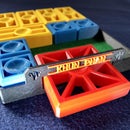
Step 10: Color Variants


Runner Up in the
Books and Bookshelves Contest


