

Introduction: Burning Bootloaders Into AVRs Using Arduino


This instructable is the result of my failure with Optiboot(8Mhz) bootloader on ATmega8. While trying that, the clock fuse had been accidentally set to 16MHz which prevented me from using my AVR because I didn't have a 16MHz oscillator and my AVR would only boot up if I provided it an external 16MHz oscillator. While looking up for multiple solutions, I finally stumbled upon this link!
This instructable aims at the usage of two Arduinos, one as a programmer and the other as a pre-built Arduino circuit. Therefore method is a real help for those who have multiple Arduinos but no programmers such as USBasp etc. Now coming back to my ATmega8, since it required a 16MHz oscillator and Arduinos have them soldered in at the respective pin for ATmega328, wouldn't it be wise to use ATmega8 in place of ATmega328 because both have the same pin configuration? Now my external oscillator issue was solved and hence I proceeded with everything as shown in this instructable.
I'd like to add that this procedure will work with all the AVRs having the same pin configuration as that of ATmega328. In other words, your AVR has to be pin compatible with ATmega328. In my knowledge, this includes all the variants of ATmega8, ATmega328, ATmega48 and ATmega88. There may be others as well. If you know them, comment them down.
Step 1: Gather Around Some Stuff


The best thing about this method for burning bootloaders is that it doesn't require even require a single electronic component. All that it requires are only the basics!
Requirements:
- Male to Male Jumper Wires - 6
- AVR Chip (in which bootloader is to be burnt)
I'll be proceeding with the instructable by taking the ATmega8 as an example. The AVR should be pin compatible with ATmega328.
- Arduino UNO(or any Arduino with 28 Pin IC Base)
Make sure that its ATmega328 is removable and not SMD. It will be used to insert your AVR and to burn a bootloader in it .I'll be referring to this board as Arduino-1 throughout this instructable.
- Another Arduino (any version capable of storing ArduinoISP)
This Arduino board will be used as an ISP because I don't have one. If so, then simply hook up your ISP with the other Arduino. I'll be calling it Arduino-2 throughout this instructable.
Now that you have all the prerequisites, let's move on and start tackling the problem head on!
Step 2: Replacing the Arduino IC

Pick up Arduino-1, remove its IC(ATmega328) and insert your AVR in its place. The IC can be easily removed using tweezers by applying leverage at one of its ends and slowly pushing in the tweezers below the IC.
After that, insert your AVR in the correct indentation according to the IC base.
Step 3: Using Arduino As an ISP
If you have an ISP beforehand, skip this step! If not, then proceed with this.
Arduino IDE has a lot of useful sketch examples pre-installed. One of them is the ArduinoISP sketch which configures Arduino in such a way that it acts as an ISP. Therefore, to make your Arduino an ISP, simply upload ArduinoISP sketch to it.
In our case, this sketch has to be uploaded to Arduino-2.
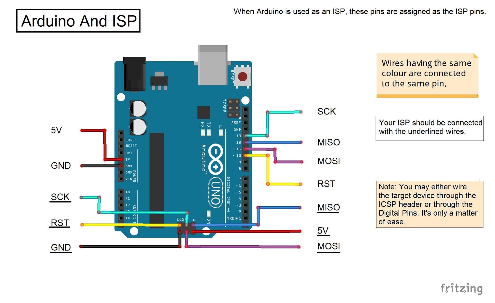
The pin assignments of Arduino when it acts as an ISP are shown above in the form of pictures. Refer to them for better understanding of its wiring.
Here is the code for ArduinoISP if you are unable to find it!
// This sketch turns the Arduino into a AVRISP
// using the following arduino pins:
//
// Pin 10 is used to reset the target microcontroller.
//
// By default, the hardware SPI pins MISO, MOSI and SCK pins are used
// to communicate with the target. On all Arduinos, these pins can be found
// on the ICSP/SPI header:
//
//               MISO °. . 5V (!) Avoid this pin on Due, Zero...
//               SCK   . . MOSI
//                     . . GND
//
// On some Arduinos (Uno,...), pins MOSI, MISO and SCK are the same pins
// as digital pin 11, 12 and 13, respectively. That is why many tutorials
// instruct you to hook up the target to these pins. If you find this wiring
// more practical, have a define USE_OLD_STYLE_WIRING. This will work even
// even when not using an Uno. (On an Uno this is not needed).
//
// Alternatively you can use any other digital pin by configuring software ('BitBanged')
// SPI and having appropriate defines for PIN_MOSI, PIN_MISO and PIN_SCK.
//
// IMPORTANT: When using an Arduino that is not 5V tolerant (Due, Zero, ...)
// as the programmer, make sure to not expose any of the programmer's pins to 5V.
// A simple way to accomplish this is to power the complete system (programmer
// and target) at 3V3.
//
// Put an LED (with resistor) on the following pins:
// 9: Heartbeat   - shows the programmer is running
// 8: Error       - Lights up if something goes wrong (use red if that makes sense)
// 7: Programming - In communication with the slave
//
#include "Arduino.h"
#undef SERIAL
#define PROG_FLICKER true
// Configure SPI clock (in Hz).
// E.g. for an attiny @128 kHz: the datasheet states that both the high
// and low spi clock pulse must be > 2 cpu cycles, so take 3 cycles i.e.
// divide target f_cpu by 6:
//     #define SPI_CLOCK            (128000/6)
//
// A clock slow enough for an attiny85 @ 1MHz, is a reasonable default:
#define SPI_CLOCK 		(1000000/6)
// Select hardware or software SPI, depending on SPI clock.
// Currently only for AVR, for other archs (Due, Zero,...),
// hardware SPI is probably too fast anyway.
#if defined(ARDUINO_ARCH_AVR)
#if SPI_CLOCK > (F_CPU / 128)
#define USE_HARDWARE_SPI
#endif
#endif
// Configure which pins to use:
// The standard pin configuration.
#ifndef ARDUINO_HOODLOADER2
#define RESET     10 // Use pin 10 to reset the target rather than SS
#define LED_HB    9
#define LED_ERR   8
#define LED_PMODE 7
// Uncomment following line to use the old Uno style wiring
// (using pin 11, 12 and 13 instead of the SPI header) on Leonardo, Due...
// #define USE_OLD_STYLE_WIRING
#ifdef USE_OLD_STYLE_WIRING
#define PIN_MOSI	11
#define PIN_MISO	12
#define PIN_SCK		13
#endif
// HOODLOADER2 means running sketches on the atmega16u2
// serial converter chips on Uno or Mega boards.
// We must use pins that are broken out:
#else
#define RESET     	4
#define LED_HB    	7
#define LED_ERR   	6
#define LED_PMODE 	5
#endif
// By default, use hardware SPI pins:
#ifndef PIN_MOSI
#define PIN_MOSI 	MOSI
#endif
#ifndef PIN_MISO
#define PIN_MISO 	MISO
#endif
#ifndef PIN_SCK
#define PIN_SCK 	SCK
#endif
// Force bitbanged SPI if not using the hardware SPI pins:
#if (PIN_MISO != MISO) ||  (PIN_MOSI != MOSI) || (PIN_SCK != SCK)
#undef USE_HARDWARE_SPI
#endif
// Configure the serial port to use.
//
// Prefer the USB virtual serial port (aka. native USB port), if the Arduino has one:
//   - it does not autoreset (except for the magic baud rate of 1200).
//   - it is more reliable because of USB handshaking.
//
// Leonardo and similar have an USB virtual serial port: 'Serial'.
// Due and Zero have an USB virtual serial port: 'SerialUSB'.
//
// On the Due and Zero, 'Serial' can be used too, provided you disable autoreset.
// To use 'Serial': #define SERIAL Serial
#ifdef SERIAL_PORT_USBVIRTUAL
#define SERIAL SERIAL_PORT_USBVIRTUAL
#else
#define SERIAL Serial
#endif
// Configure the baud rate:
#define BAUDRATE	19200
// #define BAUDRATE	115200
// #define BAUDRATE	1000000
#define HWVER 2
#define SWMAJ 1
#define SWMIN 18
// STK Definitions
#define STK_OK      0x10
#define STK_FAILED  0x11
#define STK_UNKNOWN 0x12
#define STK_INSYNC  0x14
#define STK_NOSYNC  0x15
#define CRC_EOP     0x20 //ok it is a space...
void pulse(int pin, int times);
#ifdef USE_HARDWARE_SPI
#include "SPI.h"
#else
#define SPI_MODE0 0x00
class SPISettings {
public:
  // clock is in Hz
  SPISettings(uint32_t clock, uint8_t bitOrder, uint8_t dataMode) : clock(clock){
    (void) bitOrder;
    (void) dataMode;
  };
private:
  uint32_t clock;
friend class BitBangedSPI;
};
class BitBangedSPI {
public:
  void begin() {
    digitalWrite(PIN_SCK, LOW);
    digitalWrite(PIN_MOSI, LOW);
    pinMode(PIN_SCK, OUTPUT);
    pinMode(PIN_MOSI, OUTPUT);
    pinMode(PIN_MISO, INPUT);
  }
  void beginTransaction(SPISettings settings) {
    pulseWidth = (500000 + settings.clock - 1) / settings.clock;
    if (pulseWidth == 0)
      pulseWidth = 1;
  }
  void end() {}
  uint8_t transfer (uint8_t b) {
    for (unsigned int i = 0; i < 8; ++i) {
      digitalWrite(PIN_MOSI, (b & 0x80) ? HIGH : LOW);
      digitalWrite(PIN_SCK, HIGH);
      delayMicroseconds(pulseWidth);
      b = (b << 1) | digitalRead(PIN_MISO);
      digitalWrite(PIN_SCK, LOW); // slow pulse
      delayMicroseconds(pulseWidth);
    }
    return b;
  }
private:
  unsigned long pulseWidth; // in microseconds
};
static BitBangedSPI SPI;
#endif
void setup() {
  SERIAL.begin(BAUDRATE);
  pinMode(LED_PMODE, OUTPUT);
  pulse(LED_PMODE, 2);
  pinMode(LED_ERR, OUTPUT);
  pulse(LED_ERR, 2);
  pinMode(LED_HB, OUTPUT);
  pulse(LED_HB, 2);
}
int error = 0;
int pmode = 0;
// address for reading and writing, set by 'U' command
unsigned int here;
uint8_t buff[256]; // global block storage
#define beget16(addr) (*addr * 256 + *(addr+1) )
typedef struct param {
  uint8_t devicecode;
  uint8_t revision;
  uint8_t progtype;
  uint8_t parmode;
  uint8_t polling;
  uint8_t selftimed;
  uint8_t lockbytes;
  uint8_t fusebytes;
  uint8_t flashpoll;
  uint16_t eeprompoll;
  uint16_t pagesize;
  uint16_t eepromsize;
  uint32_t flashsize;
}
parameter;
parameter param;
// this provides a heartbeat on pin 9, so you can tell the software is running.
uint8_t hbval = 128;
int8_t hbdelta = 8;
void heartbeat() {
  static unsigned long last_time = 0;
  unsigned long now = millis();
  if ((now - last_time) < 40)
    return;
  last_time = now;
  if (hbval > 192) hbdelta = -hbdelta;
  if (hbval < 32) hbdelta = -hbdelta;
  hbval += hbdelta;
  analogWrite(LED_HB, hbval);
}
static bool rst_active_high;
void reset_target(bool reset) {
  digitalWrite(RESET, ((reset && rst_active_high) || (!reset && !rst_active_high)) ? HIGH : LOW);
}
void loop(void) {
  // is pmode active?
  if (pmode) {
    digitalWrite(LED_PMODE, HIGH);
  } else {
    digitalWrite(LED_PMODE, LOW);
  }
  // is there an error?
  if (error) {
    digitalWrite(LED_ERR, HIGH);
  } else {
    digitalWrite(LED_ERR, LOW);
  }
  // light the heartbeat LED
  heartbeat();
  if (SERIAL.available()) {
    avrisp();
  }
}
uint8_t getch() {
  while (!SERIAL.available());
  return SERIAL.read();
}
void fill(int n) {
  for (int x = 0; x < n; x++) {
    buff[x] = getch();
  }
}
#define PTIME 30
void pulse(int pin, int times) {
  do {
    digitalWrite(pin, HIGH);
    delay(PTIME);
    digitalWrite(pin, LOW);
    delay(PTIME);
  } while (times--);
}
void prog_lamp(int state) {
  if (PROG_FLICKER) {
    digitalWrite(LED_PMODE, state);
  }
}
uint8_t spi_transaction(uint8_t a, uint8_t b, uint8_t c, uint8_t d) {
  SPI.transfer(a);
  SPI.transfer(b);
  SPI.transfer(c);
  return SPI.transfer(d);
}
void empty_reply() {
  if (CRC_EOP == getch()) {
    SERIAL.print((char)STK_INSYNC);
    SERIAL.print((char)STK_OK);
  } else {
    error++;
    SERIAL.print((char)STK_NOSYNC);
  }
}
void breply(uint8_t b) {
  if (CRC_EOP == getch()) {
    SERIAL.print((char)STK_INSYNC);
    SERIAL.print((char)b);
    SERIAL.print((char)STK_OK);
  } else {
    error++;
    SERIAL.print((char)STK_NOSYNC);
  }
}
void get_version(uint8_t c) {
  switch (c) {
    case 0x80:
      breply(HWVER);
      break;
    case 0x81:
      breply(SWMAJ);
      break;
    case 0x82:
      breply(SWMIN);
      break;
    case 0x93:
      breply('S'); // serial programmer
      break;
    default:
      breply(0);
  }
}
void set_parameters() {
  // call this after reading paramter packet into buff[]
  param.devicecode = buff[0];
  param.revision   = buff[1];
  param.progtype   = buff[2];
  param.parmode    = buff[3];
  param.polling    = buff[4];
  param.selftimed  = buff[5];
  param.lockbytes  = buff[6];
  param.fusebytes  = buff[7];
  param.flashpoll  = buff[8];
  // ignore buff[9] (= buff[8])
  // following are 16 bits (big endian)
  param.eeprompoll = beget16(&buff[10]);
  param.pagesize   = beget16(&buff[12]);
  param.eepromsize = beget16(&buff[14]);
  // 32 bits flashsize (big endian)
  param.flashsize = buff[16] * 0x01000000
                    + buff[17] * 0x00010000
                    + buff[18] * 0x00000100
                    + buff[19];
  // avr devices have active low reset, at89sx are active high
  rst_active_high = (param.devicecode >= 0xe0);
}
void start_pmode() {
  // Reset target before driving PIN_SCK or PIN_MOSI
  // SPI.begin() will configure SS as output,
  // so SPI master mode is selected.
  // We have defined RESET as pin 10,
  // which for many arduino's is not the SS pin.
  // So we have to configure RESET as output here,
  // (reset_target() first sets the correct level)
  reset_target(true);
  pinMode(RESET, OUTPUT);
  SPI.begin();
  SPI.beginTransaction(SPISettings(SPI_CLOCK, MSBFIRST, SPI_MODE0));
  // See avr datasheets, chapter "SERIAL_PRG Programming Algorithm":
  // Pulse RESET after PIN_SCK is low:
  digitalWrite(PIN_SCK, LOW);
  delay(20); // discharge PIN_SCK, value arbitrally chosen
  reset_target(false);
  // Pulse must be minimum 2 target CPU clock cycles
  // so 100 usec is ok for CPU speeds above 20KHz
  delayMicroseconds(100);
  reset_target(true);
  // Send the enable programming command:
  delay(50); // datasheet: must be > 20 msec
  spi_transaction(0xAC, 0x53, 0x00, 0x00);
  pmode = 1;
}
void end_pmode() {
  SPI.end();
  // We're about to take the target out of reset
  // so configure SPI pins as input
  pinMode(PIN_MOSI, INPUT);
  pinMode(PIN_SCK, INPUT);
  reset_target(false);
  pinMode(RESET, INPUT);
  pmode = 0;
}
void universal() {
  uint8_t ch;
  fill(4);
  ch = spi_transaction(buff[0], buff[1], buff[2], buff[3]);
  breply(ch);
}
void flash(uint8_t hilo, unsigned int addr, uint8_t data) {
  spi_transaction(0x40 + 8 * hilo,
                  addr >> 8 & 0xFF,
                  addr & 0xFF,
                  data);
}
void commit(unsigned int addr) {
  if (PROG_FLICKER) {
    prog_lamp(LOW);
  }
  spi_transaction(0x4C, (addr >> 8) & 0xFF, addr & 0xFF, 0);
  if (PROG_FLICKER) {
    delay(PTIME);
    prog_lamp(HIGH);
  }
}
unsigned int current_page() {
  if (param.pagesize == 32) {
    return here & 0xFFFFFFF0;
  }
  if (param.pagesize == 64) {
    return here & 0xFFFFFFE0;
  }
  if (param.pagesize == 128) {
    return here & 0xFFFFFFC0;
  }
  if (param.pagesize == 256) {
    return here & 0xFFFFFF80;
  }
  return here;
}
void write_flash(int length) {
  fill(length);
  if (CRC_EOP == getch()) {
    SERIAL.print((char) STK_INSYNC);
    SERIAL.print((char) write_flash_pages(length));
  } else {
    error++;
    SERIAL.print((char) STK_NOSYNC);
  }
}
uint8_t write_flash_pages(int length) {
  int x = 0;
  unsigned int page = current_page();
  while (x < length) {
    if (page != current_page()) {
      commit(page);
      page = current_page();
    }
    flash(LOW, here, buff[x++]);
    flash(HIGH, here, buff[x++]);
    here++;
  }
  commit(page);
  return STK_OK;
}
#define EECHUNK (32)
uint8_t write_eeprom(unsigned int length) {
  // here is a word address, get the byte address
  unsigned int start = here * 2;
  unsigned int remaining = length;
  if (length > param.eepromsize) {
    error++;
    return STK_FAILED;
  }
  while (remaining > EECHUNK) {
    write_eeprom_chunk(start, EECHUNK);
    start += EECHUNK;
    remaining -= EECHUNK;
  }
  write_eeprom_chunk(start, remaining);
  return STK_OK;
}
// write (length) bytes, (start) is a byte address
uint8_t write_eeprom_chunk(unsigned int start, unsigned int length) {
  // this writes byte-by-byte,
  // page writing may be faster (4 bytes at a time)
  fill(length);
  prog_lamp(LOW);
  for (unsigned int x = 0; x < length; x++) {
    unsigned int addr = start + x;
    spi_transaction(0xC0, (addr >> 8) & 0xFF, addr & 0xFF, buff[x]);
    delay(45);
  }
  prog_lamp(HIGH);
  return STK_OK;
}
void program_page() {
  char result = (char) STK_FAILED;
  unsigned int length = 256 * getch();
  length += getch();
  char memtype = getch();
  // flash memory @here, (length) bytes
  if (memtype == 'F') {
    write_flash(length);
    return;
  }
  if (memtype == 'E') {
    result = (char)write_eeprom(length);
    if (CRC_EOP == getch()) {
      SERIAL.print((char) STK_INSYNC);
      SERIAL.print(result);
    } else {
      error++;
      SERIAL.print((char) STK_NOSYNC);
    }
    return;
  }
  SERIAL.print((char)STK_FAILED);
  return;
}
uint8_t flash_read(uint8_t hilo, unsigned int addr) {
  return spi_transaction(0x20 + hilo * 8,
                         (addr >> 8) & 0xFF,
                         addr & 0xFF,
                         0);
}
char flash_read_page(int length) {
  for (int x = 0; x < length; x += 2) {
    uint8_t low = flash_read(LOW, here);
    SERIAL.print((char) low);
    uint8_t high = flash_read(HIGH, here);
    SERIAL.print((char) high);
    here++;
  }
  return STK_OK;
}
char eeprom_read_page(int length) {
  // here again we have a word address
  int start = here * 2;
  for (int x = 0; x < length; x++) {
    int addr = start + x;
    uint8_t ee = spi_transaction(0xA0, (addr >> 8) & 0xFF, addr & 0xFF, 0xFF);
    SERIAL.print((char) ee);
  }
  return STK_OK;
}
void read_page() {
  char result = (char)STK_FAILED;
  int length = 256 * getch();
  length += getch();
  char memtype = getch();
  if (CRC_EOP != getch()) {
    error++;
    SERIAL.print((char) STK_NOSYNC);
    return;
  }
  SERIAL.print((char) STK_INSYNC);
  if (memtype == 'F') result = flash_read_page(length);
  if (memtype == 'E') result = eeprom_read_page(length);
  SERIAL.print(result);
}
void read_signature() {
  if (CRC_EOP != getch()) {
    error++;
    SERIAL.print((char) STK_NOSYNC);
    return;
  }
  SERIAL.print((char) STK_INSYNC);
  uint8_t high = spi_transaction(0x30, 0x00, 0x00, 0x00);
  SERIAL.print((char) high);
  uint8_t middle = spi_transaction(0x30, 0x00, 0x01, 0x00);
  SERIAL.print((char) middle);
  uint8_t low = spi_transaction(0x30, 0x00, 0x02, 0x00);
  SERIAL.print((char) low);
  SERIAL.print((char) STK_OK);
}
//////////////////////////////////////////
/////////////////////////////////////////
///////////////////////////////////
////////////////////////////////////
void avrisp() {
  uint8_t ch = getch();
  switch (ch) {
    case '0': // signon
      error = 0;
      empty_reply();
      break;
    case '1':
      if (getch() == CRC_EOP) {
        SERIAL.print((char) STK_INSYNC);
        SERIAL.print("AVR ISP");
        SERIAL.print((char) STK_OK);
      }
      else {
        error++;
        SERIAL.print((char) STK_NOSYNC);
      }
      break;
    case 'A':
      get_version(getch());
      break;
    case 'B':
      fill(20);
      set_parameters();
      empty_reply();
      break;
    case 'E': // extended parameters - ignore for now
      fill(5);
      empty_reply();
      break;
    case 'P':
      if (!pmode)
        start_pmode();
      empty_reply();
      break;
    case 'U': // set address (word)
      here = getch();
      here += 256 * getch();
      empty_reply();
      break;
    case 0x60: //STK_PROG_FLASH
      getch(); // low addr
      getch(); // high addr
      empty_reply();
      break;
    case 0x61: //STK_PROG_DATA
      getch(); // data
      empty_reply();
      break;
    case 0x64: //STK_PROG_PAGE
      program_page();
      break;
    case 0x74: //STK_READ_PAGE 't'
      read_page();
      break;
    case 'V': //0x56
      universal();
      break;
    case 'Q': //0x51
      error = 0;
      end_pmode();
      empty_reply();
      break;
    case 0x75: //STK_READ_SIGN 'u'
      read_signature();
      break;
    // expecting a command, not CRC_EOP
    // this is how we can get back in sync
    case CRC_EOP:
      error++;
      SERIAL.print((char) STK_NOSYNC);
      break;
    // anything else we will return STK_UNKNOWN
    default:
      error++;
      if (CRC_EOP == getch())
        SERIAL.print((char)STK_UNKNOWN);
      else
        SERIAL.print((char)STK_NOSYNC);
  }
}
Did this step already? Well that was quick! Proceed to the next step.
Step 4: Wiring Up the Arduino


We are almost halfway!
By referring to the above wiring diagram, connect your Arduino-1 with Arduino-2.
In this step, all that we're doing is connecting the pins of the AVR directly to Arduino-2. Note that Arduino-1 doesn't play any more role than that of supplying an external oscillator in this case. I'm only using it to get female headers for the pins of the AVR inserted in it, and because it has in-built oscillator circuitry. The main schematic from which this setup has been derived has been attached to this step.
If you intend to use your programmer rather than Arduino and are feeling out of place, then don't worry, refer to the diagrams for ISP to Arduino connections which are in this step as well as in the previous step.
Step 5: Burning the Bootloader


Considering you've done everything correctly up till now , we can proceed with the burning of the bootloader into our AVR.
Follow these steps to do so:
- Connect your PC with Arduino-2.
- Open Arduino IDE, no matter which version, and do the following.
- Select the board whose bootloader is to be burnt in the AVR. For example, as shown in the picture, you'll choose Arduino UNO if you're burning the bootloader onto ATmega328 because Arduino UNO is based around ATmega328 and therefore it's bootloader will be the same.
- Set the COM Port to Arduino-2's COM port. In my case, it was COM1. Yours might differ.
- Set the Programmer as "Arduino as ISP".
- Hit Burn Bootloader under Tools menu.
After clicking on "Burn Bootloader", the burning will begin. You should see the constant blinking of Rx and Tx LEDs on Arduino-2. After about half a minute you should also get a message saying "Done Burning Bootloader".
I would like to add that I didn't upload any official board's bootloader onto my ATmega8! I wanted to use the internal oscillator of my ATmega8 because I don't have any oscillator. Therefore I used a different bootloader. The method I used is covered over here. Keep in mind that the wiring used here is the same as the one used there. Therefore you can continue using the wiring you've done till now to proceed with that method.
That concludes this step.
Step 6: Congratulations!
Phew! That was some work! Anyways, now your desired bootloader has been burnt into the inserted AVR successfully and it is up to you whether you use it in combination with Arduino-1 or in other circuits. I was able to get my two ATmega8s in working condition and replace a busted ATmega328 of an Arduino UNO(Arduino-1).
I have embedded the video of the ATmega328, in which I have burnt the bootloader, programmed with Blink sketch.
Wondering About Sketch Uploading?
I'd like to add that sketches can be uploaded to the AVR using the identical setup you used to burn the bootloader. However, instead of clicking on "Burn Bootloader", you use "Ctrl+Shift+U" key combination to upload the opened sketch onto the AVR. All this key combination does is that it tells the IDE to upload the sketch using the programmer.
I'd like to write more but I think that I've written all there is to write in this instructable. If you think I'm missing something, you're more than welcome to mention suggestions!
I'd appreciate it if you support me on Patreon.
By:
Utkarsh Verma
Thanks to Ashish Choudhary for lending his camera and to Abhishek Kumar for lending his Arduino(Arduino-1).

Participated in the
Fix It Contest


