

Introduction: Designing Parts for CNC Machining - the Basics


As I've expanded the tools and machines I use in my day to day making, I've had a keen interest in CNC and automated machining. After getting experience in Laser Cutting and 3D Printing I thought CNC machining would be an easy next step to make! However, I find that there are quite a lot of limitations and considerations inherent of CNC machining which serve as a barrier of entry for many hobbyists, preventing them from accessing the value of CNC machines for projects! Learning how and when to best use this type of machining was a bit of a struggle, so I thought that an Instructable was a good way for me to summarize and put together my research for anyone interested getting started.
At the end of the Instructable, I will also design a part for CNC machining and show you how to using Fusion360 for CAD and CAM.
In this Instructable, I'm aiming to compile everything you need to know before getting started with basic part design for CNC machining and all the tips and tricks I know of. I'm currently a University of Melbourne student and avid hobbyist so I'm always learning new things and will try to update this Instructable to reflect those new learnings!
Supplies
CNC Machine
CAD/CAM Software (Fusion360 can do both and is free for students!!)
Machinable material - wood stock, aluminum block (depends on machine capabilities)
Step 1: Lathe Instead?
If your desired part is symmetrical around a line and can be created by a solid of revolution, it will likely be easy and more efficient to machine your part by turning rather than CNC machining. Details perpendicular to this line like attachment holes can also be added later using a drill press to achieve good results. Further, due to the freer nature of lathe working, more liberties can be taken with the use of undercuts and overhangs that may be harder for CNC machines that are constrained to just three dimensions.
Step 2: Material Choice
CNC machining can use wood, plastic, and metal so material choice is quite broad. There are a lot of considerations for the general use of your component that you'll need to identify such as load requirements, durability, and tolerance - which all must be considered whilst manufacturing. In general, it's easier to get tighter tolerances with metal than plastics since vibration is less pronounced and plastics often start to deform at lower temperatures.
If precision is paramount then metals such as aluminum will outperform almost all plastic options.
Step 3: Dimensions of Block/part
When machining the part, it is best practice to ensure that the part does not go right to the edges of the block, as these sides will then be unable to be machined - leaving an uneven surface finish. Instead, as little as 1mm of external trim should be included so the machine bit can surface every edge. Similarly, as the component will need to be clamped to the table of the CNC machine, the block must extend taller than the machinable area such that it can be clamped securely without interfering with the path of the bits during machining.
Step 4: No Hidden Internal Geometries
As the standard CNC machine operates in three dimensions, XYZ, internal geometries that are possible in additive manufacturing such as 3D printing, are not feasible. Parts with hidden interior curves/channels or other features really should be approached with different manufacturing techniques OR can be done by a CNC in two parts as if creating a mold. That way you can clamp the two separate parts together which will seal and create the hidden internal geometries you're after. It will be difficult to get this precise and many alignment pegs should be used if you take this approach to ensure accuracy.
Some internal geometry such as overhangs can be achieved with an undercut, of which I'll go into detail in step 11, however, in most cases this is limited and should be avoided if possible. Side holes and external overhangs can also be achieved by simply reorienting the part in the machine, although when rotating precision is lost.
Step 5: Limit Number of Part Rotations
Now, whilst a component can be rotated as many times as desired to machine every possible face, this is not good practice at all and repeated readjustment will come at the cost of precision. Every time the part is adjusted, another potential for inaccuracy is introduced and it is extremely difficult and in many cases not feasible to get perfect alignment following one. Therefore, in all cases where the part can be completed with less reorientations and without sacrificing necessary features, it should be a priority. This can be done by changing side attachment holes into slots, or rethinking part design to accommodate.
If rotation of the part cannot be avoided to get the final product that is needed, a jig or alignment system should be implemented to avoid misalignment. On a woodworking CNC, guide holes and pegs can be added to the baseboard in places where the tool path won't intersect, or for metal works, separate alignment jigs can be used.
Step 6: Internal Pockets
For pockets carved out of your part, it's generally standard to have a ratio of width to depth of around 1:4 or 1:5. This is important as the deeper the cavity into your part, issues such as tool deflection (bending) and chip buildup can become significant. The greater stresses associated with these larger depths will also be strenuous to your CNC machine and bits, which could result in breaking tool heads over time.
Step 7: Isolated Wall Thickness
When designing parts for CNC machining, the accuracy of the end product is often the main goal, so you should ensure you take all the necessary precautions to ensure this. Having large sections of freestanding wall can be detrimental to the accuracy of the part. This is because the large unsupported sections can be prone to vibration and therefore be unpredictable and imprecise to machine. Workarounds to increase stiffness include increasing the thickness of the walls and adding supportive elements such as triangle plates connecting the wall and the rest of the part.
With most materials this shouldn't be an issue if all the walls are at least a few millimeters thick and the machine is precise, however softer materials such as plastics are more prone to warping and deformation, so more precaution should be taken. A good tip is to try and keep a maximum thickness to height ratio of 1:4.
Step 8: Internal Edges

Vertical Edges
For internal vertical edges, it is impossible to get a perfect 90 degree corner, as every bit no matter the size will have some radius. Therefore, some radius in required in the design. It is good practice to keep this radius as large as possible so that a large bit can create it and tool changing isn't necessary for the part to be made. Further, the tool must be the same size, or smaller than the fillet radius for it to be created. However, it is always better to use a tool that is smaller than the fillet radius so that it can take a smooth path and not have to instantaneously change direction at the corner. This is to avoid tool damage and wear.
If fitment with a 90 degree component is necessary, the toolpath can be extended using a Dogbone corner which will remove enough material for a rectangular insert as shown above.
Horizontal Floor Edges
Fillets on on the horizontal floor edges of a pocket or cutout should be avoided where possible. They are quite difficult to machine unless you have the correct size in a bullnose bit. If fillets can't be avoided, larger fillet radii are preferred like with the vertical edges, so that large tools can create them gradually.
Step 9: External Edges
Vertical Side Edges
When designing a part, it is always good to break the edges to give a more finished part, this is best done on the side edges by using fillets or chamfers. As these are external features, their radii/angles are not as significant as internal corners and any radius should be easily machinable.
Top Edges
Top edges are better broken by using a chamfer since surfacing a fillet will take a long time and chamfers will usually achieve a much similar result. When adding chamfers, 45 degrees is standard and is best practice since most chamfer bits will be designed this way.
Step 10: Holes
When designing the holes that will be included in your part, it's useful to think of the physical manufacturing of it and use sizes that are consistent with standard drill bits. Unlike 3D printing, where the nozzle can create shapes and geometries that are 1 of 1 to your liking, CNC machines can only easily make holes that are inline with drill bit sizes. Whilst smaller bits can gradually widen holes to non-standard dimensions - this will add time, cost, and complexity and you're more likely to damage tools doing this. Therefore, it is in your best interest to design parts with machining in mind and try to align with the standard sizing metric/imperial when possible.
As for length, ideally holes would have a diameter to depth ratio of roughly 1:4, however in practice 1:12 is pretty typical and greater depths commonplace. A lot of the time the added depth is somewhat redundant in terms of strength though so minimize this where you can.
Step 11: Avoid Overhangs

Undercuts add greatly to the difficulty of the machining process, especially if you're inexperienced and have limited tools. To create them, either specialized tools or rotation of the part will be required, so it's best to avoid these where possible and minimize the amount required to be cut when they aren't avoidable.
They can be done by a large cylindrical cutting bit on a smaller shaft, which can move sideways into the material and remove it whilst leaving an overhang above, however, if this needs to be done on the interior of the part there must be enough clearance on the top surface hole for the entire bit to enter - restricting what can be achieved.
Step 12: Avoid Raised Design Features/Text
A way to save time and material when machining a logo or other design feature is to choose engraving instead of embossing. This will mean that much less material will have to be used.
It is important to also be weary of the detail of the design. Adding many intricate and fine details to emboss or imprint will be very difficult and will likely require changing orientations and switching to smaller tools. So it's best to keep features large and simple for CNC machining where possible.
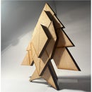
Step 13: Part Designed With Fusion360


The above is an example of a part I've design for CNC machining - note the use of the aforementioned features and considerations. The top surface edges are deburred with a 45 degree chamfer, pocket depth is not too deep and all of the walls are suitably thick to ensure rigidity. Also, the integral edges are filleted at a large radius such that the arc is achievable for most standard sized bits. Lastly, a slot in the front edge is used as opposed to a screw hole as it allows for the part to be completed without any changes of orientation
Step 14: Using CAM


CAM in Fusion360 is really seamlessly integrated. In the top left you can chage the tab from "Design" to "Manufacture" and be instantly greeted with CAM tools for your current part. Creating the tool path in the software is quite an involved process, and due to the case specific nature that depends on your part, tools, materials and available bits, it's hard to detail the exact steps you'll need to do. Fusion360 CAM software is incredibly complex and deep, however I will try to give a rough outline of the process as more relevant to you info regarding each step can be easily found online:
First a new setup should be created - in this step you'll provide values for the size of the stock you're machining, as well as the zero point for the process. This is the point that your CNC machine will reference during machining so make sure you choose this suitably.
Now, all of the tools that you will require should be added to the library. This can be done manually or by searching and downloading the data from the manufacturer of you bits. The information includes RPM, size, cooling and more so it's easiest to import data for the tools you have than to measure them yourself and find specifications to input.
Once your tools are all setup, the different cutting procedures can be defined as well. Adaptive Clearing will likely be the most commonly used especially for simple parts like the example I've provided. This generates a path to clear large sections of material. There are also options to such as 2D chamfer to create a chamfer pass along a set loop from your part.
Once you've set up your tool paths, you can run a preview simulation to ensure that all of the passes are behaving as expected, and then the gcode or script can be exported to your CNC device.
Step 15: Conclusion

As a hobbyist and student I'm always learning new things and I've no doubt left out some key details that may be helpful or bonus tips that can help kickstart a project. Therefore, please use the comments to add any of your own experience and knowledge! This Instructable is a summary of my own knowledge, experience, and research, however, there are many comprehensive sources and videos that detail more aspects of CNC milling and include graphics regarding some of the ideas that I'm describing. The following are great resources that I have used in the past and found helpful;
- Hubs, How to design parts for CNC machining, https://www.hubs.com/knowledge-base/how-design-parts-cnc-machining/
- Adam Bender, How to Design Parts for CNC Machining, https://www.youtube.com/watch?v=qx_qqVmjCc0
- Hubs, Tolerances Explained in CNC Machining (what affects them), https://www.youtube.com/watch?v=zj1_uPSP6i8
- NYC CNC, Fusion 360 CAM Tutorial for Beginners! FF102, https://www.youtube.com/watch?v=Do_C_NLH5sw
Please feel free to add more resources in the comments! Hope this Instructable is helpful to some of you :)
Participated in the
CNC Student Design Challenge


