

Introduction: Topology Optimization for Bookends | 3D Printing Project


The recent rise of consumer AI has brought a lot of interesting new approaches to creative work. A lot of the time AI is looked down upon in this field, so I wanted to enter this competition and see how AI could be used productively as part of the design process. I wanted to create some bookends and like the abstract look many modern pieces have, which I found AI to be a great part of. So follow along as I make some 3D printable bookends with the AI capabilities built into Fusion360.
Supplies
Materials
- PLA filament ( ~ 100g)
Equipment
- 3D Printer
Software
- Fusion360 (free for students)
- Cura Slicer (or your preferred)
Step 1: Get Some Dimensions
Starting out the first step is always to figure out the scope of the project and do some research and early drawings. I made some quick sketches and testing some dimensions to see what I wanted to work with before starting the design process. Doesn't have to be much, but it's always good to start by putting pen to paper and spend 10-15 minutes figuring things out to make the CAD process smoother.
Step 2: Get the General Shape

For this project I'll be using the Topology Optimization tool in Fusion360 - which works by simulating the stresses within a part - and allowing you to choose to remove material on a scale depending on it's contribution to the strength of the part. This way, we can remove the least important material up to some threshold and (hopefully) end up with some funky looking abstract pieces that look great and are functionally strong due to keeping all the important bits!
To start off, I sketch up the inside of the book ends, this is the part that will interface with the books. I designed a simple L shape with a thin 3mm bottom for the books to sit on and keep the uprights secure. Then I just use a simple extrude to create the 3D shape necessary (extrude half the width each direction for ease later)
Step 3: Add Backing Material


Now we want to add some structure to the back of the bookends that we can use with our topology optimization - the point of the project! I tried to create something with smooth lines - almost could be ready as a bookend just like that! Doing this means I'm not left with any jagged edges on the outside at the end if there are areas where little material is removed.
To make the backing I'm going to use a base sketch and a loft along a guide rail. To start to do this we need a closed sketch on the base, and another sketch on the back of the L shape we just made. The sketch on the back of the L is just the same size rectangle as our dimensions from earlier, the base is just the shape you want the base to be! It's better to have something without sharp edges so I use splines and make sure all endpoints are tangent by making the control points parallel to the segment connecting. It's useful to use the mirror tool on this to get both sides symmetric easily and quickly - a construction line down the middle to reflect through is the easiest way.
Step 4: Create Guideline

Now we have the shapes that we will be lofting together to create the back segment, we want to create a rail for this loft to run along to get the right shape for our design.
Since we extruded the L piece symmetrically, we can just start a new sketch on the XZ plane and it will be centered on the other sketches we've been making. This sketch just needs to go from the top of the rectangle to the furthest end of the base - how it gets there is up to your design preference! Just make sure that the line is perpendicular to both loft sketches and is tangent throughout its entirety.
Step 5: Create Body


Now we have all of the sketch components we need, we can simply select the base and back sketches and the loft, and add our guideline sketch as a rail. This will complete our solid and we can move onto the next part of the design process.
Step 6: Simulation Setup

Now we want to change from the design window to the simulation window, we can do this by clicking in the top left. On the menu that appears just click shape optimization, which will load your active body into the simulation software.
Before we can begin with the optimization, we must define a few things: namely our physical constraints and forces. Firstly, I constrained the base of the model by clicking the face, then constraints up top, and selecting fixed for the z plane. In addition to this, I fix the two points in all dimensions at the front corner to make sure the object is fully locked in place.
Now, by clicking on the faces the books will interface with, and then selecting loads, we can add some linear forces to the plate. The forces you use for this doesn't exactly matter but I used 10N for the base and 30N for the side plate.
Lastly, by selecting the shape optimization tab on the top bar and selecting preserve region, we can add an exclusion zone where the optimization won't touch. I covered the main book side with this so that only the support structure will change shape.
Step 7: Running the Simulation


Now that everything is set up, we can run the simulation and see what we get! Once the results page opens, we can use the slider in the bottom right hand corner to remove either the most or least structurally important pieces. Obviously for this project we want to remove the material that contributes the least amount of strength per unit volume. This is a cool way to generate unique and interesting mesh shapes - but also has more practical applications in weight and material saving so this process helps save a bunch of filament for 3D printing.
Step 8: Iterate Finalize


The design process of this is very iterative - feel free to run the simulation multiple times - adjusting the forces and dimensions to see what shapes it will produce until you find something you like. Also you should go back to the initial design and make any amendments you see fit if the simulation gives you some inspiration.
Once you're happy with the results, select the promote button under result tools in the bottom left (selected in image) and then change the drop down to add the mesh to the design window.
Step 9: Reduce / Separate Face Groups


Now, we could leave it there and just export what we generated to be manufactured, but I think we can do better. The way it is created leaves quite a few rough patches that don't look the best and whilst we want to keep the geometric appearance, if we make it a little smoother I think the end result will be a bit more aesthetically pleasing.
First, I used the reduce tool to reduce the number of faces slightly, this resulted in a little bit of a cleaner look and got rid of some of the small sharp protrusions which I didn't quite like.
Then, using the Generate Face Groups tool, I separate the object into 6 face groups so I can control which ones are smoothed since I want the side that interface with the book and the shelf to remain perfectly flat. I can then use the Separate tool to split the face groups into individual mesh entities for smoothing.
Step 10: Smooth Mesh


Then, I used the smooth function on each of the meshes to get everything a little more rounded on the selected face groups that I want to be. i.e. the main feature at the back of the design. How much you smooth is down to preference and this step is really just for aesthetics. Once all bodies are smooth we can use the combine tool to re-attach all of the individual face groups to the main body.
Note: You may have to use the Repair tool after this to make sure the mesh is closed using the Stitch & Repair dropdown.
Step 11: Level Base


Next up, I use the Plane Cut tool on the base to make sure everything is level again - even though we separated everything and didn't smooth the base, it's good to make sure by doing this step. I do the Plane Cut just through the base of the model, such that it's just above the highest part of the base. Then use the repair tool to patch the hole I've left where I cut.
Step 12: Export & Slice

Now the mesh is complete! All that's left to do is to export the mesh as an STL file and then run it through your slicer. I use Cura slicer, but any slicer software should be more than capable.
Print Settings
Infill %: 10%
Infill Pattern: Tri-hexagonal
Resolution: Low (0.28mm Layer height)
Vertical Shell Thickness: 0.8mm
Horizontal Shell Thickness: 1.12mm
Step 13: Print to Finish


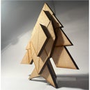
That's it! Send it off to the printer and hopefully get great results! I print on a stock Ender 3 V2 and the standard print speed completed one bookend in 4 hours, however I'm sure with a better tuned printer these could be done much quicker.
Hope you enjoyed reading and learned something new!
Download here: https://makerworld.com/en/models/230597

This is an entry in the
Made with AI - Autodesk Design & Make - Student Contest


