

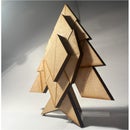
Introduction: Pinball Arcade Machine - Lasercut & 3D Printed


As a current student I feel like I've somewhat missed the heyday of classic arcade - that's why I was so enthusiastic to get on board with this design challenge and make a pinball machine of my very own from scratch using the tools available to me. In this Instructable, I'll show how I went about making my very own tabletop pinball machine with laser cutting and 3D printing technology. I'm currently a student at the University Of Melbourne.
Supplies
Materials
- 3mm MDF
- 6mm MDF (can be replicated with multiple 3mm sheets glued together)
- 3mm Acrylic
- 6.3mm Aluminium rod (2x 28mm lengths)
- PLA filament
- Craft Glue
- Spring (roughly 10mm outer diameter and 30mm in length)
- 10mm diameter steel ball (ball bearing)
Equipment
- Laser Cutter
- 3D printer
- Hand saw
Software
- Fusion360 (free for students!)
- Cura (any slicer for 3D printing works)
- CorelDraw
Step 1: Planning
As with every good project, the first step is planning. I find it's best to start with a blank piece of paper and an idea, and just try to fill out the details from there. Usually the first thing to get down is shape - then size. And after that I try to give some perspectives as I envisage how it'll all come together.
As part of this step I drew a rough idea of what I wanted for the pinball layout. For example I plotted out obstacles, holes, and the points for each in a rough pattern. After a few iterations I took a photo so I can reference the image in Fusion360
Step 2: Importing Reference Image


Now it's time to transfer over to CAD - with my software of choice Fusion360. The easiest way to get started is by inserting one of your reference images into the project so you can base your sketches off this accordingly. This is super easy using the CANVAS tool in the software and selecting your file, then the plane you want to import it onto, in this case; XY.
Step 3: Scaling Reference Image

Once we get our picture imported and in the right place, it's time to scale it to the desired size. Since my picture was cropped to the actual size I made a rectangle of the desired size and then scaled the image until it fit perfectly onto it. It doesn't have to be exact since the sketch is just a guide so you should aim to be accurate in CAD not be 100% in line with your drawing.
Step 4: Tracing Your Obstacles


Now everything is imported and scaled it's time to trace out the obstacles. I chose to use only arcs for these curves and it turned out well - splines can also be used but I kept to arcs to keep it simple and easy to compute/export since not all software reads splines well. If you do however, choose to use splines there is a handy Autodesk Spline to Polyline tool you can use for export, I'll link it here
Step 5: Extrude/ Pieces


Once done, I extruded my obstacles to the dimensions I wanted to work with to get a better look at how everything will run, and so I can gradually build up the model in Fusion360. I added a rectangle sketch the size of the outline for the acrylic sheet that will go on top, as well as the rolling floor that the ball will run on and drop through the holes of. I didn't worry about designing the details such as numbering as I added that in later when I had a better view of the project as a whole. I also keep each extrusion as a separate body so I can view them independently later on to see inside or from different angles if need be.
Step 6: Use Materials


As I do this, I also make use of the appearance tool. By right clicking on a component and selecting appearance you can use a range of material renders from Fusion360s library. You don't have to do this, but I find that it helps to visualize the final project coming together and is good motivation to keep at it.
Step 7: Ball Return


As my pinball machine has no electronic components, I decided to make the scoring system a little easier. Each time your ball drops through one of the holes in the board - you gain whatever the score marked for that hole with the harder to reach holes earning more. After going through these holes, the ball will be collected and roll to the collection at the front left of the machine to be played again for more points and so on. However, once the ball ends up in the hole at the bottom between the paddles the game is over and the final score is reached. I think this is a great way to keep score without having electronics as it's easy to know when you've scored and how much, and you can make a note before playing the ball again so you don't have to worry about keeping a mental note as you play or having someone watch. Finally to complete the main assembly of the game I added a floor to the bottom of the ball return to keep everything contained.
Step 8: Holes for Paddles


What good is a pinball machine without some paddles to keep the ball rolling!? Next I made a cut right through to the bottom floor of the assembly that I could insert the metal rod in. This serves two purposes; first it act as the pivot point for the paddles which we're about to introduce, and secondly it also helps to line up all of the layers of the model - since we're stacking multiple MDF sheets to construct.
When using a laser cutter, the width of the laser itself isn't negligible which is called kerf. This means that inner radii will be slightly larger than modelled and outer radii slightly smaller as the laser takes some material away like any cutting tool. This varies with machine, but is important to keep in mind. I ended up under sizing these holes because of this and to ensure a perfect fitment.
Step 9: Paddles


The paddles are designed to be lasercut as well. I designed one by itself and then used the mirror tool to get the other. It's helpful to toggle the visibility of different sketches/bodies as you make parts like this that will interface with others to see how everything will come together. I also took this time to model in the pins for their hinges using a simple extrude.
Step 10: Outside Panels


As clear from the pictures so far, there are plenty of holes for the ball to escape from between the obstacles. To remedy this and complete the design of the machine, I'll be adding four 3mm panels to go around the main assembly. Holding everything in place and finishing the style.
Just like the other parts, I create a sketch on the plane that I'm working with, and toggle the visibility of other parts to make sure that everything clears any relevant parts and lines up nicely with the rest of the build. To hold the outsides secure I use tabs, and going back to the kerf discussion from earlier on, I'll be oversizing my tabs and under sizing my slots by around 0.4mm for a snug fit.
Step 11: Numbers

Before we get everything ready to cut, the numbering for each hole needs to be added. I did this in much the same way as the backboard design - using the curved text tool to follow the circular path of each hole.
Step 12: Exporting DXF for Lasercutting
Exporting files for lasercutting is really easy in the software - just right-click each of your sketches and select the "export as DXF" option. It's good to also keep track of which pieces are to be cut out of 3mm and 6mm MDF so it's easier to compile on the laser cutting machine later.
Step 13: Laser Cutting

Once you have your completed DXF files, you're ready to set up for laser cutting! I used a Trotec laser cutter for this project, so the process was as easy as importing my selection into CorelDraw on the connected computer – and then printing the page to Trotec Job Control.
It's always important to make sure your page is the right size for your laser cutter dimensions so that everything runs smoothly and predictably, and components don't go beyond the workable area.
Step 14: Back Panel Design


Now to add some style to the design! As I'm going with a sort of retro look with this machine, I chose some retro styling cues and font for my backboard to match. Using the curved text tool, I bound the text to some arcs in the sketch and then chose a fitting font. Then some other simple shapes were added with the basic line and arc tools to complete the look. Once completed, it's extruded a couple of millimeters to be 3D printed.
Step 15: Ball Launcher


One of the final components we need to complete the machine is a launcher for the ball. For this, I had to make an extra hole in the front panel for the handle to go through. I designed a simple launcher with a cradle and handle section. The entire handle is small enough to pass through the hole for assembly, but a cap can be added once it is through to ensure it doesn't go too far into the tray and become stuck. This launcher will be 3D printed from PLA plastic.
Step 16: 3D Printed Supports


Lastly, we need to design some supports to hold the center assembly at the right height to meet flush with the top of the exterior panels. These are just some small 7.5mm x 7.5mm studs that align with the base profile and can be glued in place on the side panels.
Step 17: 3D Printing

First of all, all of our 3D printed components can be exported as STL files to be read by our slicer. You can just right-click on the bodies in Fusion360 and the hit "Export as mesh" to export STLs. Then just open these models in the slicer and arrange your buildplate. All of the 3D printed components for this project were printed with standard PLA with pretty basic settings. To slice and print everything it took around 3 hours using stock print speed and lower quality since there aren't many intricacies.
Print Settings
Infill: 20%
Brim: Yes
Quality: Low (0.28mm)
Supports: No
Rafts: No
Step 18: Obstacles Glue Up


Now we have all our cutout pieces, we first need to glue up the obstacles so they end up the right height, i.e. two 6mm panels for the 12mm needed. The craft glue is quick and easy for this MDF
Step 19: Centre Assembly Construction


To start the construction of the center assembly, the pins were cut to length with the handsaw and then hammered into the bottom 6mm piece, then the next one was slid on top and gently tapped into place. The rolling floor then could be attached in the same way. At last, once secure the bottom floor could be glued on, as well as the obstacles onto the rolling floor.
Step 20: Preparing External Panels


Backboard
To get the backboard all glued as necessary, I just used a ruler to measure and made some marks with a pencil. I also used the curved pieces as stencils to trace the curved line the letters will sit on which helped with lining everything up easily. Looking back, all of the separate letters were a little painful to glue up and could've been done more easily with paint/stencils, but I think the 3D effect was worth it :)
Side Panels
The side panels both need the little 3D printed supports attached to them so that the center assembly can rest on them and stay supported. The craft glue is fine for this and doesn't take long to dry at all, just make sure everything is lined up and there will be enough room for the center piece.
Step 21: Final Assembly


Last but not least, we can assemble the full model! Make sure that the spring is placed around the launcher before the handle goes through to the outside of the frame, and then glue the cap to keep everything secured. Then the side profiles were attached and the center assembly placed inside and onto the supports. This is all glued into place except for the acrylic piece. In my design there is no hole to drop the ball back into the game so each time the acrylic simply can be lifted to place the ball and before sitting it back in it's place during play. This solution works best for me and in my opinion looks the cleanest, but if you want to glue it down you can always add a hole in the acrylic to drop the ball in the launcher.
Step 22: Time for Pinball!
That's it! I hope you enjoyed following my build and if you make anything similar using my Instructable, please let me know if you do! Enjoy Pinball and please watch along above to see it in action! :)
Second Prize in the
Arcade Student Design Challenge


