

Introduction: E-Paper Clock


This project is an e-Paper clock and weather station that automatically sets itself (via GPS) and can be built to last about 6 months on 4 AAA batteries. It purposefully does not need any network connections for the sake of security and reliability.
Features include:
- Autoset (via GPS)
- Current temperature.
- Current humidity.
- A pressure graph showing pressure over the last 25 hours.
- Sunrise and sunset times
- Current moon phase
- Select between 12h or 24h modes.
- Select between English and metric units.
I put together two main variants of the project: "easy" and "low power". The "easy" version is based on the Arduino Nano. The intent with this variation is to minimize cost, part count and build complexity. The downside is that you'll need to power the clock from a USB 5V adapter.
The "low power" version uses a 32k oscillator to maintain accurate timing with very little power. This oscillator allows the clock to run on batteries.
Both versions are designed to be buildable on a breadboard for experimentation. The final board is designed to be buildable by any of several techniques: prototype boards, CNC milling, chemical etchings, or ordering a PCB from the provided design files.
Step 1: "Easy" Version Parts List


If you are building the easy version, this step lists the parts you will need. If you are building the low power version, skip to the next step.
- Arduino Nano (or clone) ($3). I went with a clone board on Amazon but with May 2022 prices, I'd consider ebay as well.
- Waveshare 2.9 in EPaper Module ($22). Purchase direct from Waveshare or from amazon.
- Adafruit MS8607 Pressure / Humidity / Temperature Sensor ($15). I chose this one because of its low power draw.
- Any basic GPS module with 9600 Baud TX ($12). I went with this one
- Circuit Board: This might be a prototype board OR a piece of copper clad for CNC OR you might opt to order a prefabricated PCB from the design files.
- A couple ofpush switches: These are used to change the UTC time offset and display preferences.
- Materials to build a case: I provide .3mf, .scad, and .dxf files if you would like to use a 3D printer, laser cutter, or CNC machine (I used a 3D printer and CNC), but you can also do a personalized case.
- USB charger and cable: To power the unit
Step 2: "Low Power" Version


If you are building the "easy" version above, skip this step.
You will need these same parts from the easy version:
- Waveshare 2.9 in EPaper Module ($22). Purchase direct from Waveshare or from amazon.
- Adafruit MS8607 Pressure / Humidity / Temperature Sensor ($15). I chose this one because of it's low power draw.
- Circuit Board: This might be a prototype board OR a piece of copper clad for CNC OR you might opt to order a prefabricated PCB from the design files.
- A couple of push switches:. These are used to change the UTC time offset and display preferences.
- Materials to build a case: I provide .3mf, .scad, and .dxf files if you would like to use a 3D printer, laser cutter, or CNC machine (I used a 3D printer and CNC), but you can also do a personalized case.
You will also need:
- Atmega328P DIP version($2): You can alternately opt for an SMD package version but soldering on the 32k crystal will be harder.
- 32768 Hz Crystal (<$1): This oscillator is key to low power in the design.
- Adafruit GPS Module ($30): This module is a bit higher quality than the one in the "easy" version in that it can track more satellites (for faster lock), provides an enable pin (for low power) and a port for keeping its memory active (for fast relock). If all those features don't justify the added cost for you, you can hack a cheaper module to do the job by adding your own enable FET. I explain how in an upcoming step.
- LED + Resistor The bare Atmega328P has no way to tell you if it's working, locked up, etc. The blinking light thus provides a 1ms / second "heartbeat" that consumes almost no power but provides useful feedback.
- A couple of 10 uF and a 100 nF capacitors to smooth the supply voltage.
- Batteries: I went with 4 AAA but anything that gets you 5-7V should work. I would expect roughly 5 mah per day of battery usage.
- Optional: A 3x2 pin header for programming the chip via ICSP. If you are fine with removing the Atmega328P to reprogram it, then you can skip this connector.
- Optional: A 1x2 pin header for UART debugging. You will only need this if the board is acting erratically.
Step 3: Arduino Mini Version


I said there were two versions but this is a bonus one (V2.5?). It exists because we live in a "parts drought" where chips like the Atmega328P go out of stock for long periods.
You can run this version with the "easy" firmware or, if you have the soldering confidence, you can solder a 32k crystal on the microcontroller (as shown in the photo above) and go with the 32k version of the firmware (more details on the next section).
The schematic above is wired with a "cheap GPS" solution but you can also go with the Adafruit GPS if you replace the GPS part of the schematic with the Adafruit setup (as illustrated in the previous step's schematic).
Step 4: Optional: Cheap GPS

That Adafruit GPS unit is expensive ($30) compared to the competition ($12). If you don't think the added features (described in the low power parts section) are "worth it" you can drop in any GPS module that transmits NMEA strings at 9600 baud (which is most of them).
But now there is a new problem to solve: most of these units lack an enable/disable pin and GPS units typically consume 30-100 mA of power. You can hack a disable switch in using a N-MOSFET (or similar). The schematic above shows the basic idea. You can also try it out in falstad
This power switch circuit has trade-offs. See Appendix B for details if you are interested in learning more about them.
Step 5: Low Power Hardware Mods


If you are building the "easy" version, you don't need to read this section. For the low power version, these mods will improve battery life significantly.
For illustration, we will assume power is coming from a set of AAA batteries which can supply 1000 mAh. Let's assume you are using the 32k Adafruit version and are doing no mods. Here is an example power breakdown:
- "Sleeping/Off" CPU, GPS, MS8607, and EPaper: Measured at 30-70 uA (we'll say 50uA)
- Screen Update: 5 mA for 2 seconds once per minute: 5 * 2 / 60 = 166 uA
- GPS Update: 50 mA for 10 seconds once per day: 50 * 10 / 86400 = 6 uA
- MS8607 LED: 100 uA
- Adafruit GPS pullup resistor: 500 uA
Thus we have (50 + 166 + 6 + 100 + 500) = 822 uA of average current draw which amounts to ~50 days of power.
Remove the MS8607 LED and the GPS pullup and we reduce power usage to 222 uA which is ~187 days of power, significantly more!
- First, I suggest removing the LED from the MS8607 as shown in the photo.
- The pullup resistor on the Adafruit GPS was added by Adafruit designers to make the EN pin optional. But it has a downside: when you pull it to ground (to disable the GPS) - about 500uA is lost to heat in that pullup resistor! Since the enable pin is actively driven this design, you can remove the resistor as shown in the photo.
- Pro mini mods: Google search "Arduino mini low power" for details, but basically, you'll want to remove the voltage regulator and LED to reduce power usage. We are instead using the MS8607's voltage regulator (3.3V, 35-55 uA power lost at idle) to power the pro mini.
- In the pro mini photo, I also removed the crystal oscillator to prep the chip for a 32K crystal. Remove this crystal only for the 32k crystal version and only after the fuses have been reprogrammed on the pro mini as explained later.
Step 6: Firmware
I have attached precompiled .hex files for both the nano and 32k crystal versions. (either will work for the pro-mini, use the nano version if you are not sure which to use).
If you want to build/modify the source yourself, it is located at https://github.com/mattwach/epaper_clock
OPTIONAL: Building the .hex firmware files yourself
Note that this code does not use Arduino libraries because the resulting code would be too big to fit on the Atmega328P (and it's my personal preference). Instead it's written in C using the same AVR base libraries that Arduino also uses as a base. If you want to compile the code, you will need to install the (free) avr-gcc tools, clone the epaper project sources. then go to the firmware/ directory and type:
makeIf the code builds, you'll want to open the Makefile and look at these options:
# This is the Low-power stand alone chip configuration.
CLOCK_MODE ?= USE_32K_CRYSTAL
UART_MODE ?= HARDWARE_UART
F_CPU ?= 8000000

# This is the easy-to-build firmware that is based on an Ardino Nano
#CLOCK_MODE ?= USE_CPU_CRYSTAL
#UART_MODE ?= SOFTWARE_UART
#F_CPU ?= 16000000
If you are building the 32k crystal firmware, the configuration is already correct. If building the nano version, you'll need to comment out the 32k lines and uncomment the nano lines, then
make the firmware again.
There is also a special debug mode that dumps log messages over the hardware UART at 9,600 baud. You can ignore it for now but keep it in mind as something that might be useful later:
# Uncomment to activate debug via the UART TX (9600 baud)
#DEBUG_CFLAG := -DDEBUG
Finally, you can decide how often the GPS should be activated by changing a couple of variables. Currently, it runs once per day but will run less often if GPS takes a long time to lock in order to reduce battery drain. Read all about it in src/gps.c.

Step 7: Firmware Upload Using ICSP

This section is for those uploading code to a stand-alone Atmega328P chip (or burning Arduino Pro mini fuses). If you are uploading to an Arduino Nano skip ahead to the next step.
You'll need what is called an ISP (or ICSP) programmer. You can buy these for around $10 on amazon or make one yourself with a spare Aruino Uno/Nano The options continue but I'll leave that to a Google search for "Arduino ISP Programmer". Note that a lot of these guides assume your real goal is to install a bootloader but for our case, no bootloader is needed as you'll be uploading the .hex file directly with the ICSP.
Brownout detection
On my particular Atmega328P, the brownout detection as set to 3.5V (old version of the chip? A clone?) so I disabled brownout detection with this command:
/usr/bin/avrdude -patmega328p -cusbasp -Uefuse:w:0xFF:mYour options may be different depending on your ISP programmer (the -c option). You probably won't need it but just in case...
Step 8: Using Avrdude
The popular Arduino IDE uses a free utility named avrdude to upload the hex files it creates to your Uno/Nano/etc. You can also download and use avrdude directly from the commandline instead. To get the correct options for the tool you can:
- Run an upload (blinking light demo or something) with the Arduino IDE with output logging turned on, then copy the command it used. OR
- Read the official avrdude docs OR
- Read one of the many avrdude tutorials on the internet.
For your reference, here is the avrdude command I used for the nano version (via make upload):
/usr/bin/avrdude \
		-v \
		-patmega328p \
		-carduino \
		-P/dev/ttyUSB0 \
		-b57600 \
		-D \
		-Uflash:w:epaper_firmware_using_arduino_nano.hex:i
and this is what I used for the ISP version:
/usr/bin/avrdude \
		-v \
		-patmega328p \
		-cusbasp \
		-Uflash:w:epaper_firmware_using_32k_crystal.hex:i
I'm using Linux. Mac and Windows also work fine but options like -P will be different (i.e. possibly -PCOM1 in windows).
Step 9: 32K Crystal


If you are building the "easy" version, skip this step. If you are using the 32k crystal firmware, the crystal will need to be installed for the firmware to function.
First (!) You'll also want configure the internal fuses on your ATMega328P to use the internal 8 Mhz crystal. It's important to do this step first because the 32k crystal is replacing any existing crystal. If you don't change these fuses, the chip will become non responsive until you reconnect a 8 or 16 Mhz oscillator which would be an annoying pain.
As far as I know, the Arduino pro mini also needs ISP to change the fuses (but I could be wrong). I looked up "Arduino ISP" to get the correct pin mappings for interfacing an ISP connector with a breadboard as shown in the photo.
With my ISP programmer connected, I check the current fuse configuration with this command:
$ avrdude -patmega328p -cusbasp
...
avrdude: safemode: Fuses OK (E:FF, H:DE, L:E2)
The L:E2 is the setting you want for internal 8mhz. If your value is different, you can update it with a command similar to this one:
/usr/bin/avrdude -patmega328p -cusbasp -Ulfuse:w:0xE2:m
Then recheck.
After the fuses are setup, you can solder on the crystal. Attaching the crystal directly to the microcontroller pins is recommended to reduce stray capacitance. Too much capacitance and the crystal will take longer to start oscillating (or fail to start).
Step 10: Optional: First Steps

Refer to the schematic of your chosen design in step 1, step 2 or step 3.
- You can verify that things are OK so far on a breadboard by connecting just a LED/Resistor from D5 to ground and uploading the firmware. If all is well, the LED will briefly flash once per second.
- Next, you can add the EPaper display. None of the data will be correct on the display but it should show some some data.
- Next, add the PHT module and verify it's working.
- and finally the GPS module.
At this point, we are "done and can transfer everything over to a more permanent fixture.
Step 11: Circuit Board Assembly


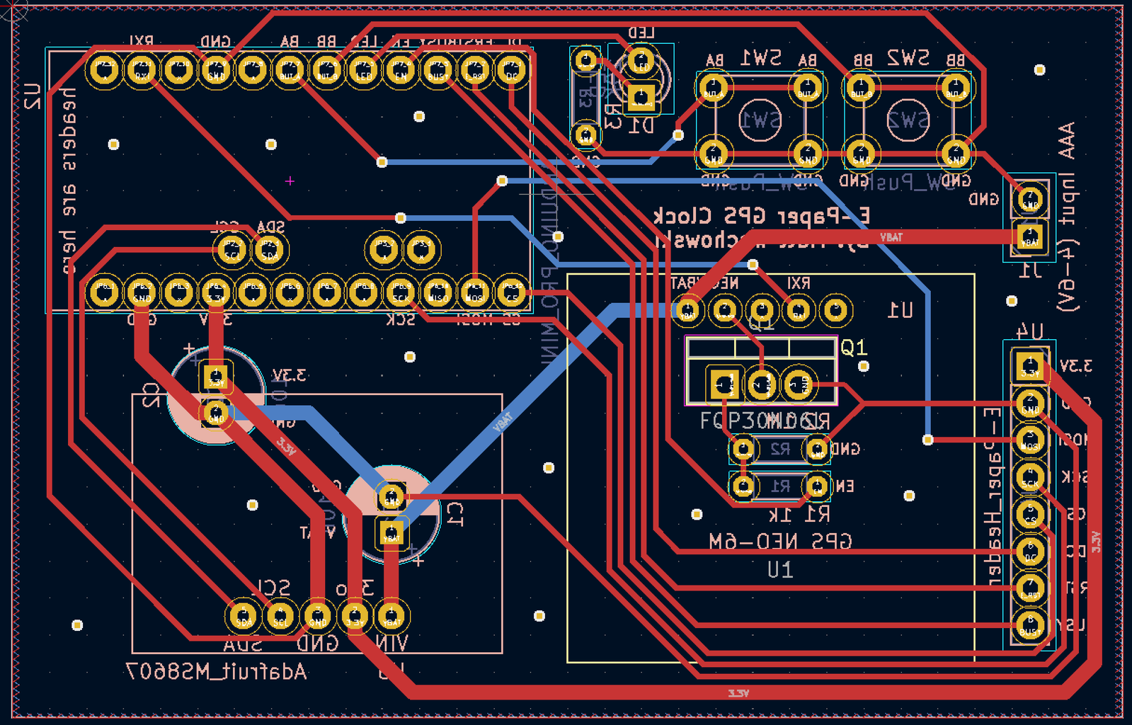


You have the options of using a perf board, cutting the board with a CNC or sending the design to a fab for manufacture.
The Kicad design files can be found in the schematic/ directory. There are three hardware flavors to choose from (all shown from behind since that is how you would wire them by hand).
I cut the ATMega328P version with my CNC machine. If you have not used CNC to cut a PCB and are interested, try a google search for "3018 PCB" and you'll find many videos and articles on the topic. Isolation clearances are 0.4mm but you can go narrower (probably not wider). I used Flatcam to convert Kicad's Gerber output to G-Code. I included my Flatcam project in the schematic/ directory. In that directory, I also included the G-Code files I sent to my 3018 CNC machine.
Step 12: Case Design


You can design any type of case you want and I encourage you to be creative here! But I'm also sharing how I made my case. All of my design files are in the case_design/ folder of the project.
My design uses a 3D printed support structure and two CNC parts: a top cover and front panel. The CNC parts are made of wood because I thought it would look nicer than plastic. I designed the whole thing upfront in OpenSCAD.
I printed the main structure with 0.2mm layer height. On my 3D printer, the print took a little over 5 hours.
I used OpenSCAD's "projection" feature to created 2D DXF files for the top cover and front plate. At this point, I would normally use a free program called "Carbide Create" to make G-Code for the CNC machine. But my face plate has a 45 degree chamfer to the screen and Carbide Create is too basic of a program to handle this well (at least my Google searches through forums on their website led me to that conclusion). So I tried a different program called "CamBam" and it worked very well. CamBam is not free but you can use it 40 times for free.
Step 13: Appendix A: Optional Clock Drift Correction
// Clock drift correction
// If your clock runs too fast or too slow, then you can enable these
//#define CORRECT_CLOCK_DRIFT
// number of seconds that a second should be added or removed
//#define CLOCK_DRIFT_SECONDS_PER_CORRECT 1800
// define this if the clock is too slow, otherwise leave it commented out
//#define CLOCK_DRIFT_TOO_SLOW
You can uncomment the top two #define statements above to enable the correction. You only uncomment CLOCK_DRIFT_TOO_SLOW of your clock is falling behind. If your clock is too fast, leave it commented. The only thing left to do is set CLOCK_DRIFT_SECONDS_PER_CORRECT...
The math way
Wait about a day then see how much the clock has drifted. For example, you might wait 23 hours. If at that point you see the clock has lost 10 seconds, then your correction would be:
(3600 * 23) / 10 = 8280 seconds per correction.#define CORRECT_CLOCK_DRIFT #define CLOCK_DRIFT_SECONDS_PER_CORRECT 8280 #define CLOCK_DRIFT_TOO_SLOW
The non-math way
Just try a number like 5,000 and refine it as you note that the clock is still to fast or too slow. Still too slow? Try 2,500. Too fast? Try 10,000. Keep notes and iteratively refine it to some acceptable value just like the number guessing games you may have played at some point.
Step 14: Appendix B: Cheap GPS Power Control (The Tale of the BS170 N-MOSFET)


Revisiting the power control circuit described in the "Cheap GPS" step, the power cutoff circuit above is called a "low side switch". It's benefit is that it's relatively easy to understand and the part count is low. That said, there are some design concerns:
- The ground of the GPS is not tied to GND but on the MOSFET drain. This means that the UART signal from the GPS to the microcontroler will have the MOSFET voltage drop added to it (Vds), increasing noise sensitivity and possibly causing outright errors
- You would not want to use this design if your microcontroller inputs are specified as 3.3V maximum (the ATMega328P I chose doesn't have this limitation).
- 3.3V (EN pin above) is not a very strong turn-on voltage for every MOSFET.
But hey, the UART is a digital signal and the ground difference isn't that much so maybe it will work anyway? I tried it and it worked fine... at first but I came to discover over time that it was not reliable. To understand why, we refer to the characteristic curves of the BS170 I originally chose as my N-MOSFET.
At 3.3V on the X axis we will be sitting between the 3.0 and 4.0V lines on the graph. So maybe we'll get 100mA? Maybe enough?
My multimeter was telling me the GPS consumes 40-60ma but I think this is an average value. Depending on what the GPS was trying to do, it just needed more current than the transistor was willing to allow, thus the GPS ground (MOSFET drain) voltage would rise. This created both UART errors and reduced overall voltage to the GPS unit which would sometimes still sort of work and other times go into a reset loop.
One solution would be to go with a "high side" power circuit with an additional P-MOSFET on top to make it happen. See the schematic image above. This eliminates the separate ground issue and provides a full 5V (battery) gate voltage swing, which will turn the associated P-MOSFET fully on.
Here is an example high side design in falstad.
But in my optimism, I had already ordered PCBs with the lowside wiring so my secondary solution was to abandon the BS170 and go with a FQP30N06L instead. This higher-current MOSFET (max 30A!) seems like serious overkill, and it is but its curves look much better. Around 10A of current allowance at 3.3V which is a 100x improvement over the BS170 and should now be plenty; and indeed the instabilities have not returned.

![Tim's Mechanical Spider Leg [LU9685-20CU]](https://content.instructables.com/FFB/5R4I/LVKZ6G6R/FFB5R4ILVKZ6G6R.png?auto=webp&crop=1.2%3A1&frame=1&width=306)


