

Introduction: ESP32 Bluetooth Controlled Car


In this project, I made an ESP32 based mobile controlled car. This is a beginner friendly project and I recommend this to anyone interested in IoT and other mobile controlled devices.
Supplies

Switch
Batteries - 4 × 1.5V
5V Power bank (5V battery is fine)
3D printed model
Caster wheel
Motor wheels
Step 1: Code for ESP32
Connect the ESP32 to your computer using a cable. I hope you have already installed all the necessary libraries and boards for ESP32. If not, please install them if you would like to continue.
So, before we begin, you will have to install this library called Bluetooth Serial. Download the .zip file and go to -
Sketch → Include Library → Add .ZIP Library... and choose the downloaded Bluetooth Serial file.
The code is very simple and easy to understand (I will explain the code step by step).
#include "BluetoothSerial.h"


BluetoothSerial SerialBT;


int C1 = 18;
int A1 = 19;
int C2 = 21;
int A2 = 22;
String SBT;


void setup() {
 Serial.begin(115200);
 SerialBT.begin("ESP32_Car");
 pinMode(18, OUTPUT);
 pinMode(19, OUTPUT);
 pinMode(21, OUTPUT);
 pinMode(22, OUTPUT);
}


void loop() {
 if (Serial.available()) {
   SerialBT.write(Serial.read());
 }
 if (SerialBT.available()) {
   Serial.write(SerialBT.read());
 }
 delay(5);
 SBT = SerialBT.readString();
 Serial.println(SBT);


 if (SBT == "f")
 {
    digitalWrite(C1, HIGH);
    digitalWrite(A1, LOW);
    digitalWrite(C2, HIGH);
    digitalWrite(A2, LOW);
 }
 else if (SBT == "b")
 {
    digitalWrite(C1, LOW);
    digitalWrite(A1, HIGH);
    digitalWrite(C2, LOW);
    digitalWrite(A2, HIGH);
 }
 else if (SBT == "l")
 {
    digitalWrite(C1, LOW);
    digitalWrite(A1, HIGH);
    digitalWrite(C2, HIGH);
    digitalWrite(A2, LOW);
    delay(200);
    digitalWrite(C1, LOW);
    digitalWrite(A1, LOW);
    digitalWrite(C2, LOW);
    digitalWrite(A2, LOW);
 }
 else if (SBT == "r")
 {
    digitalWrite(C1, HIGH);
    digitalWrite(A1, LOW);
    digitalWrite(C2, LOW);
    digitalWrite(A2, HIGH);
    delay(200);
    digitalWrite(C1, LOW);
    digitalWrite(A1, LOW);
    digitalWrite(C2, LOW);
    digitalWrite(A2, LOW);
 }

 else
 {
    digitalWrite(C1, LOW);
    digitalWrite(A1, LOW);
    digitalWrite(C2, LOW);
    digitalWrite(A2, LOW);
 }
}
Explanation
#include "BluetoothSerial.h"
Imports the Bluetooth Serial library into the code.
BluetoothSerial SerialBT;
It gives another name for BluetoothSerial (for convenience).
int C1 = 18;
int A1 = 19;
int C2 = 21;
int A2 = 22;
String SBT;
C1, A1, C2 and A2 are the inputs given to the motor driver to control the motors.
SBT is the variable which stores the signal given by the smartphone.
void setup()
void setup() {
Serial.begin(115200);
Exchanges messages with the serial monitor at a rate of 115200 bits per second.
SerialBT.begin("ESP32_Car");
This is the name of the car as seen on the smartphone.
 pinMode(18, OUTPUT);
 pinMode(19, OUTPUT);
 pinMode(21, OUTPUT);
 pinMode(22, OUTPUT);
Declares that these pins are meant for output.
}
void loop()
void loop() {
 if (Serial.available()) {
   SerialBT.write(Serial.read());
 }
 if (SerialBT.available()) {
   Serial.write(SerialBT.read());
 }
This is a very important part of the code. It might be a bit confusing at first. Basically, this piece of code allows the ESP32 to communicate with a smartphone.
delay(5);
Wait for 5 millisecond. (Optional)
SBT = SerialBT.readString();
Reads the signal as a string. When received, the signal is recognized as an integer.
Serial.println(SBT);
Writes the signal to Serial. Can be seen on the Serial Monitor.
 if (SBT == "f")
 {
    digitalWrite(C1, HIGH);
    digitalWrite(A1, LOW);
    digitalWrite(C2, HIGH);
    digitalWrite(A2, LOW);
 }
If the data received via Bluetooth reads as "f", then we give signal, to the motor driver, to rotate both motors clockwise.
 else if (SBT == "b")
 {
    digitalWrite(C1, LOW);
    digitalWrite(A1, HIGH);
    digitalWrite(C2, LOW);
    digitalWrite(A2, HIGH);
 }
If the data received reads as "b", then we give signal to rotate both motors anti - clockwise.
 else if (SBT == "l")
 {
    digitalWrite(C1, LOW);
    digitalWrite(A1, HIGH);
    digitalWrite(C2, HIGH);
    digitalWrite(A2, LOW);
    delay(200);
    digitalWrite(C1, LOW);
    digitalWrite(A1, LOW);
    digitalWrite(C2, LOW);
    digitalWrite(A2, LOW);
 }
If the data received reads as "l", then we give signal to rotate left motor anti - clockwise and right motor clockwise. There is a 200 millisecond delay to ensure enough rotation and then the motors are stopped. If the motors are allowed to rotate like front and back movement, it will turn more than the required amount.
 else if (SBT == "r")
 {
    digitalWrite(C1, HIGH);
    digitalWrite(A1, LOW);
    digitalWrite(C2, LOW);
    digitalWrite(A2, HIGH);
    delay(200);
    digitalWrite(C1, LOW);
    digitalWrite(A1, LOW);
    digitalWrite(C2, LOW);
    digitalWrite(A2, LOW);
 }
If the data received reads as "r", then we give signal to rotate left motor clockwise and right motor anti - clockwise.
 else
 {
    digitalWrite(C1, LOW);
    digitalWrite(A1, LOW);
    digitalWrite(C2, LOW);
    digitalWrite(A2, LOW);
 }
If no signal is getting received, no motors will rotate.
}
Step 2: 3D Model

I made a very simple model for the chassis using Tinkercad. It has 15% infill. You can use more infill if you want. I used less because this is just a car and won't need much strength.
Here is the link - https://www.tinkercad.com/things/4zhcfwr3tHf-3d-print/edit?returnTo=%2Fdashboard.
3D print it, make sure that you use enough infill. The sides are very thin and can break if infill is not enough.
Step 3: Circuit

The diagram above shows how the motors should be connected with the driver. Remember to check the direction of rotation of the motors before attaching them to the chassis.
ESP32 :-
Pin 18 - Motor Driver Input 1
Pin 19 - Motor Driver Input 2
Pin 21 - Motor Driver Input 3
Pin 22 - Motor Driver Input 4
Connect the ESP32 to a power bank through the USB port. (It needs more power for the Bluetooth to work)
Connect Ground of ESP32 to Ground of battery.
Battery - 4 × 1.5V = 6V
Connect the cells in series.
Step 4: Bringing Them All Together


In the 3D model, I have put 2 holes on the sides for the wires to be connected from the motor to the driver. There is a rectangular space for the placement of a switch and some wires from the battery.
The ESP32 and Driver was kept on top of the base.
The car had no balance, but it was corrected when I glued a caster wheel to the front.
The battery was glued to the back of the back of the car, here I made sure that it won't touch the ground as if it did, then it may wear and cause damage to the cells.
The power bank used to power the ESP32, was kept on top of the car.
Step 5: The App


Now, for controlling it, I am using the Bluetooth Classic which is a built - in feature of the ESP32. To give it signals for movement, I made an app using MIT App Inventor.
It took me very less time to make this app. The programming is block based which makes it even easier.
So, to build it, go to the website and click, "Create Apps" (Top - left).
Step 6: Import the App


You don't have to write the program yourself. You can just import this .aia file and you will see all the code and elements I made.
Download this .aia file -https://drive.google.com/u/0/ucid=1dZhcYcAUmSKDIXrfQUe1gtQRssRGZRM&export=download
- Click on Projects
- Click on Import project (.aia) from my computer...
Step 7: Viewing the App


Download this app on your smartphone. This is a mobile app for viewing an app made in MIT App Inventor
https://play.google.com/store/apps/details?id=edu.mit.appinventor.aicompanion3&hl=en&gl=US
After loading the app, click on Connect (top - left of your computer) - Then Click AI Companion.
A QR code and a 6 letter code will appear.
Step 8: Connect

On your phone, open the MIT AI2 Companion app.
Click on Scan QR code and scan the QR code which came on the MIT website.
or
Type the 6 letter code in the textbox.
The control program will automatically open.
Step 9: Connect the Car and App
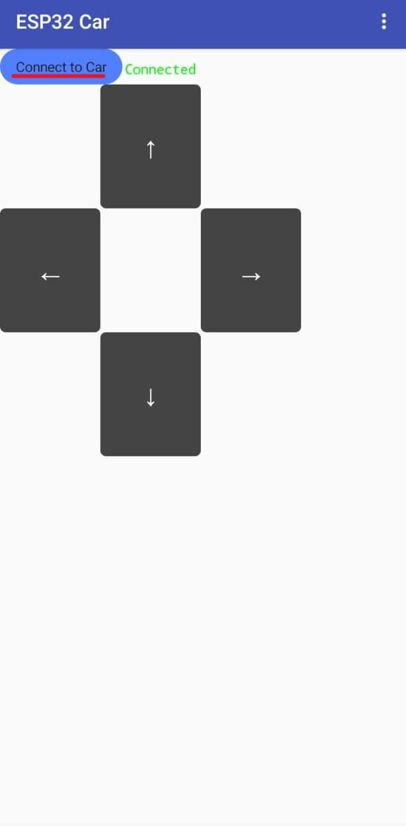
Now, in the app, you can see a button with the text "Connect to car". (Make sure Bluetooth is turned on and the app has Bluetooth permission). If you click the button, it will lead you to a list showing multiple Bluetooth devices. Select ESP32_Car from the list.
If the connection is successful, it will show "Connected" next to the button.
Now, you can use the arrow buttons to control the car.
Step 10: Demo

Step 11: Conclusion
Even though this was an easy project, I faced difficulties while trying to provide power to the ESP32 board. When you provide less than 5V, the Bluetooth does not work properly. This is the reason I used a power bank.
I hope you had a good time in making this project. If you are planning to make it, make sure you don't make the mistakes I made...
- While 3D printing, use more infill to prevent it from breaking.
- Use extra power for the ESP32.
I hope you learned something.
Happy building!
:)

Participated in the
Anything Goes Contest


