

Introduction: Simple Capacitance Meter


This instructable explains how to measure capacitance values in the range 0pF to 10uF using an Arduino and a 10nF reference capacitor.
The circuit does not use the time constant formula, or measure the elapsed time to charge a capacitor to some predetermined value.
Instead capacitance values are determined by multiplying the reference capacitance by the voltage ratio formed when the unknown capacitance is connected in series with the reference capacitor.
Construction is simple … only three solder connections are required.
Features include
- Wide range … 0pF - 10uF
- High accuracy.
- Fast and stable readings.
Other ranges are possible by changing the reference capacitor.
The estimated cost, excluding the Arduino, is less than $5.00
Images
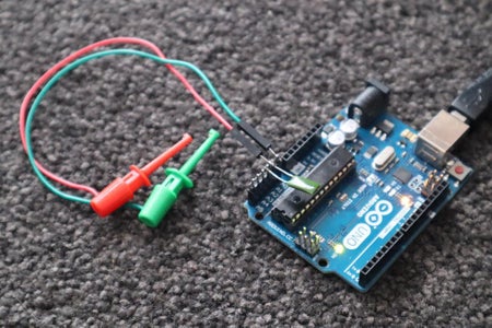
- The cover photo shows the prototype capacitance meter attached to a variable capacitor. The reference capacitor is the small brown blob.
- Photo 2 shows the final version of the capacitance meter.
- The video demonstrates the capacitance meter reading standard capacitor values.
Supplies
The followings parts were obtained from https://www.aliexpress.com
- 1 only Arduino UNO R3 with USB cable
The following parts were obtained locally
- 1 only 10nF capacitor
- 2 only mini-clips
- 3 only header pins
- hookup wire
The estimated cost, excluding the Arduino, is less than $5.00.
Step 1: Circuit Diagram


The circuit diagram is shown in photo 1.
Construction details are shown in photo 2.
Operation
The series connected capacitors form a voltage divider when A2 is forced HIGH and A0 is forced LOW.
The applied voltage is equivalent to an ADC (analog to digital converter) count of 1023
The voltage across C is equivalent to the ADC reading on pin A1.
The unknown capacitance is equal to the reference capacitance multiplied by the capacitor voltage ratio less any stray capacitance. The stray capacitance is the measurement obtained without capacitor C connected.
The actual capacitance is therefore
- C = C1*(1023-ADC)/ADC – Cstray ………………………… (1)
Following each measurement, the charge on both capacitors is removed by forcing pins A0, A1, and A2 LOW.
Step 2: Theory

This step is mathematical and may be skipped
The formula for the calculating the charge on a capacitor is
- Q = I*T = C*V ……………………………………..… (1)
where
- Q = charge in coulombs
- I = current
- T = time
- C = capacitance in farads
- V = voltage across the capacitor
The instantaneous charge on each capacitor will be the same since both capacitors receive the same charging current for the same length of time therefore
- q1 = q2 …………………………………………......….(2)
where
- q1 is the charge on C1
- q2 is the charge on C2
But:
- q1 = C1*(Vin-Vout) ……………………………….….. (3)
- q2 = C2*Vout …………………………………………. (4)
where
- q1 = charge on C1
- q2 = charge on C2
- Vin = applied voltage
- Vout = output voltage across C2
Substituting equations (3) and (4) into equation (2) and rearranging
- C2 = C1*(Vin – Vout)/Vout ………………………..…. (5)
Assuming Vin is equivalent to an ADC (analog to digital converter) count of 1023, equation (5) becomes
- C2 = C1*(1023 – ADC)/ADC …………………….….. (6)
where
- C1 = reference capacitor
- C = unknown capacitance
- 1023 = Arduino 5V
- ADC = Arduino analog to digital converter reading
The value for C2 includes the input capacitance of your Arduino ADC. This capacitance, which is in the order of 29pF, may be ignored when measuring large values of capacitance, but is significant when the capacitor values are small.
The following formula allows for this stray capacitance
- C2 = C1*(1023 – ADC)/ADC - Cstray ………………………….. (7)
Theoretical Measuring Range
The following calculations use equation (6) and assume C1=10nF
When the ADC count is 1:
C2 = 10000*(1023 -1)/1 pF
= 10 uF [1]
When the ADC count is 512
C2 = 10000*(1023-512)/512 pF
= 10nF
= reference capacitor
When the ADC count is 1022
C2 = 10000*(1023-1022)/1022pF
= 10pF [2]
Notes
[1]
Larger capacitance values require a larger reference capacitor.
[2]
When measuring low value capacitors the accuracy can be improved by using a smaller reference capacitor.
For example if C1 is 1nF then the low value resolution becomes 1pF.
Step 3: Software Installation
Method
- Download the attached file “simple_capacitance_meter.ino”
- Copy the contents into a new Arduino sketch. (Use a text editor such as Notepad++ ... not a word processor.)
- Save the sketch as "simple_capacitance_meter" (without the quotes)
- Compile and upload the sketch to your Arduino.
Attachments

Step 4: Calibration
Step 1
- Set Cstray = 0.0; in the header
- Set C1= 10000; in the header
- Compile and upload the code to your Arduino.
Step 2
- Connect a 150nF (nanofarad) capacitor between the test probes
- Open your Serial Monitor at 115200 bauds.
- Note the reading … let’s assume that the reading is 160nF
Step 3
- Change C1 in the header to read 10000*150/160
- Recompile and upload the code to your Arduino.
- C2 should now read 150nF.
Step 4
- Disconnect C2
- Note the reading … let’s assume the reading is 29pF (picofarads)
- Change Cstray in the header to read Cstray=29;
- Recompile and upload the code to your Arduino
- The reading should now read 0pF
Calibration is now complete.
- The reading should be zero with nothing connected to the probe
- The reading should be 150nF when you reconnect the 150nF capacitor
- The reading you get when you connect an unknown capacitor between the probes is the value of the unknown capacitor.
Step 5: Summary
This instructable explains how to measure capacitance values in the range 0pF to 10uF using an Arduino and a 10nF reference capacitor.
The circuit does not use the time constant formula, or measure the elapsed time to charge a capacitor to some predetermined value.
Instead capacitance values are determined by multiplying the reference capacitance by the voltage ratio formed when the unknown capacitance is connected in series with the reference capacitor.
Construction is simple … only three solder connections are required.
Features include
- Wide range … 0pF - 10uF
- High accuracy.
- Fast and stable readings.
Other ranges are possible by changing the reference capacitor.
The estimated cost, excluding the Arduino, is less than $5.00
Click here to view my other instructables.

Participated in the
Anything Goes Contest


