

Introduction: Tension Series - Floating Bed


Not being a fan of mass produced Ikea furniture boringness, I decided I was going to make myself a bed frame. And if I'm going to design and make something myself, I'll do my best to make it something unique and interesting!
I set out to design a bed frame that gave the illusion it was floating, to do away with the usually leg in each corner and try hide the base structure as best I could when viewed standing up...
(Update:
After multiple suggestions to, I added some LED strips lights around the parameter of the underneath.. really adds to the affect! Cheers to those who commented and made the suggestion!)
And this is what I came up with. Six arms reach out from a central spine to support the bed surround and headboard. These arms are pin jointed at the base, with wire rope tensioned between opposite arms to constrain their width and further rigging down to the base to create a static, level structure. The base extends out to prevent the whole thing tipping over when your sat on one edge with minimal flex.
The bed is designed around a standard 4ft6 mattress. The overall dimensions are 2120mm long and 1570mm wide, the surround sits at a height of 350mm.
The CAD model and drawings I created for this can be downloaded here:
I've also entered this into the Wood Competition, so if you feel its worthy, a vote would be very much appreciated!!
Things you'll need.
Supplys:
- 7 x 2400mm scaffold board
- 1 x 1800mm scaffold board
- Timber for the slats, I used 69x18mm lengths whitewood
- Wire rope (not exactly sure how much <20m)
- 8 x eye bolts
- 9 x turnbuckles
- Lots of wire rope grips and thimbles
- Electrical tape
- 8 x M10 30mm bolts
- 10 x M10 100mm bolts/nuts
- 4 x M10 130mm bolts/nuts
- Wood screws
- Wood Glue
- Oil/stains/varnish.
Tools I used:
- Saws (table/mitre/circular/jigsaw/hand)
- Router with bits
- Drill with bits and holesaw cutters
- Sander
- Chisels
- Screwdrivers
- Hammers
- Wire rope cutters and pliers
- Socket set/ spanners
- Clamps
- Measuring tapes/ squares/ spirit levels etc
Step 1: Design


I started with this idea of creating a bed that appeared to float from certain angles. After sometime sketching out different concepts on how this could be achieved, I moved into CAD to detail the design. From this CAD model I then created a series of drawing for each component that I would produce from the scaffolding boards. The dimension of standard scaff boards were kept in mind and used to constrain the dimensions of parts.
The arms are pin jointed rather than fixed to reduce the stresses in that area of the design. Using a pin joint means they are essentially free to rotate and so are free of moment stresses when you load the end of the arms, now the joint mainly has to deal with compression loading. To prevent the arms from rotating, cable is rigged between the opposite arms which goes into tension when the arms are loaded. And with just 4mm cable having a min breaking load of ~1000kg the structure should remain solid. Think of a boom/tower crane - same principles. If fixed at the base the arms would want to bend!
The CAD design is almost the same as what I ended up building but as you can expect there were minor changes that needed to be made along the way.. I've not had time to update the CAD model, but if you choose to use my drawings they'll be a good start.
Shown is one of the drawings I created, the rest can be downloaded in pdf. format here:
With the design sorted, it was time to start building! I've given a summary of the steps I took and the photos should help, but essential you just need to create the parts specified in the drawings.
Step 2: Prep


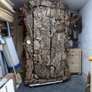
The bed will be made from 8 scaffolding planks (7 - 2400mm and 1 - 1800mm long). You can regularly pick them up cheap from reclamation/wood recycling yards, which helps keep the costs down.
I started by prepping the scaffolding boards; removing the metalwork from the ends and giving them a bit of a tidy up.
To made them easier to work with, I next cut them down to the lengths of the individual components. You can see from the included image how the 8 planks split out into the parts.
Step 3: Base


The base consists of 5 parts that you need to cut out; 2x Base Plates, 2 x Base supports and the Spine.
Base Plate:
- Mark out the part using the dimensions from the drawing
- For the recess across the width of the part, I first used a mitre saw with the depth stop engaged (set slightly short of the required depth) and made several cuts to remove the majority of the material. I then used a router to finish up the cut to the correct depth.
- For the other recess cut I had to use the router for the full cut. This meant having to do multiple passes, each taking off slightly more material. The corners were squared off with a chisel.
- I then used a jigsaw to round the ends of the 1st base plate. And then used a router with a profiling bit to copy it on the 2nd one.
- Holes for the eye bolts were then drilled with the underside recessed to allow the nut to sit sub-flush.
Base Supports:
- Mark out part
- Used the mitre saw to cut the 45° angles.
- For the central cut out, I first drilled holes in the corners and then used a jigsaw to cut it out
- Holes for the pins were the drilled out.
Spine:
- Mark out part
- Cut to the correct width using a table saw
- Jigsaw used to cut the dropped down detail.
- Holes for the pins drilled out.
With all the parts cutout I used a router to round over the edges and gave everything a sand down. I then did a dry assembly to check everything fitted together and adjusted the parts where necessary to ensure a good/tight fit.
It was then time to apply some wood adhesive, fit the parts together and clamp everything up to dry. I added some screws for good measure.
Step 4: Arms


The first 'Side Arm' you cut out will become the 'master' that will be used to made the others, so take time to get it right.
- Cut the planks to the correct width
- Mark out the part.
- Cut out the part using the appropriate saw for each cut.
- Drill the holes for the pins (adjust the diameter of this hole for whatever pin size you're using).
With the 1st one cut-out, you can use that to quickly mark out the others and then cut them to the rough shape.
Next, using a router with a profiling bit the 'master' is used as a guide to finish off the other arms and ensure they're all the same:
- Clamp the 'master' to the top of the 'rough cut' blank.
- Set the bearing on the bit so it will run around the 'master'
- The depth on my router was maxed out so I had to do the cut in two parts, removing the 'master' for the 2nd cut.
You should now have 8 Side Arms that are identical. The only difference between Side Arms (a) and (b) is the side you route a small recess in to allow a slat to be fitted.
The arms for the front and back follow the same process....
The parts were next given a quick sand and the edges rounded over. Spacers were then cutout and glued between two arms, with dowels used to add strength. I inserted a metal tube while they dried to ensure the alignment was correct.
Step 5: Slat Supports


These parts will be attached to the bed frames surround and be used to mount the slats. 2 Slat Mounts need to be made, a left and a right.
- The blanks were cut to the correct width using a circular saw with the blade set to the correct angle.
- Recesses were again cut using the same method. Multiple cuts with the mitre saw set to the required depth and then cleaned up with a chisel.
- A template was cutout of a scrap piece of wood and used with a router to cut the recesses for the slats to sit in.
The slats were also cut to the required length at this point.
Step 6: Surround/Headboard


The headboard and surround are simply lengths of plank joined using a lap joint.
Headboard:
- I used a table saw to cut multiple slits to the correct depth.
- I then chiseled the majority of the material away
- A router was setup to finish the cut off.
- The lap joint was tested and adjust to get a nice fit.
- On the bottom plank I cut a 5° bevel along the bottom edge
- Glue was applied and the two planks clamped together to dry.
Surround:
- Cut to the correct width using a circular saw.
- The mitre saw with the depth stop engaged was then used to cut multiple passes which were the tidied up with a chisel.
- The lap joint was tested and adjust to get a nice fit.
- Recesses and slots were routed in for the headboard supports and side attachments.
- The surround was glued and clamped together
Step 7: Finishing

All the parts were given a final sand down and then finished with Danish Oil to maintain a natural look.
With all the parts made we're now ready to assemble!!
Step 8: Assembly


The tubing I used for the pins (34mm dia.) was left over from my previous Scaffold Shelving project, so I started assembly by cutting the pins, 12 are needed. The arms can now be assembled to the base structure. Time to get rigging...
- I started with the 'side arms', connecting opposite arms together. The cable, with a turnbuckle inserted into the midpoint, is looped around the top pin of each arm and clamped. I wrapped electrical tape around the end aswel.
- I used a slat to set the correct width the arms are meant to be apart and tightened the turnbuckle to set this width.
- The front and back are are now rigged in the same way. At this point, the 3 sets of arms will be able to rock side to side, so we now need to rig down to the base.
- Rigging from the top pin of each arm is connected down to the end of the base stands. The arms can now be locked into a static structure by tightening the turnbuckles on apposing sides, until the level bubbles in the middle!
- With the arms set we can now add the slat mounts to each side of the frame. These simple sit into the cut-out at the top of the side arms.
- The surround is then lifted into place. Its sit on the flat portion at the top of the arms.
- I then placed the slats into the mounting points.
- The Slat Mounts and now joined to the Surround. Wooden blocks are glued and screwed between the slat mounts and surround. I did this when they were assembled on the arms rather than before to ensure alignment.
- The headboard is placed onto the surround and holes drilled through it and the headboard supports. The headboard can then be bolted in place.
- The 'Attachment' parts need to be cut-out and glued/screwed to the surround. Again, done when assembled to ensure they were in the right place between the arms.
- Holes are now drilled through the arms and attachments. A bolt is pushed through and nut tightened... the bed frame is now secured together.
- The final step was to just fine-tune the tension on the cables to level the whole bed frame out.
Update:
After multiple suggestions to, I added some LED strips lights around the parameter of the underneath..
Step 9: Conclusion
The bed frame is now complete!! I've slept in it the last few nights and not woken up in a pile of splintered wood yet, so all good!
Being a prototype design there are obviously a few things I would do differently if I made another. While you can sit right on one edge without the other side lifting, there is a small amount of flex - extending the base supports out further would improve this but then you'd compromise the 'floating affect.' Again, while you can happily sit right on the quite unsupported corners, I'd maybe change the design so that arms came out to the corner of the frame instead of front/back, middle.
Other than those points, I'm really happy with the way the design worked out!!
Hope you've enjoyed this Instructables, happy building!!

Second Prize in the
Wood Contest


